1KD-FTV LUBRICATION OIL PUMP REMOVAL
CAUTION / NOTICE / HINT
The necessary procedures (adjustment, calibration, initialization, or registration) that must be performed after parts are removed, installed, or replaced during the oil pump removal/installation are shown below.
| Replacement Part or Procedure | Necessary Procedures | Effects/Inoperative when not Performed | Link |
|---|---|---|---|
| Replacement of ECM | ·
Learning values save ·
Learning values write ·
Vehicle Identification Number (VIN) registration |
·
Engine starting ·
DTC P0630 is output |
( ) |
| Code registration (Immobiliser system) | Engine start function | See the Service Bulletin for the registration method. | |
| Replacement of engine assembly | ·
Injector compensation code registration ·
Pilot quantity learning |
Engine starting | ()
|
| Replacement of fuel supply pump assembly | Supply Pump Initialization | Engine startability | ()
|
·
Replacement of diesel throttle body assembly ·
Replacement of turbocharger sub-assembly or turbocharger variable nozzle motor |
Perform initialization | - | ()
|
| Replacement of timing belt | Mode reset operation | ·
Does not illuminate when replacement is necessary ·
Illuminates when replacement is not necessary |
()
|
for A750F:
·
Automatic transmission assembly ·
Transmission valve body assembly ·
Any of the shift solenoid valves |
Reset memory | ·
Large shift shock ·
Engine overruns |
()
|
for A750F:
Automatic transmission fluid |
ATF thermal degradation estimate reset | The value of the Data List item "ATF Thermal Degradation Estimate" is not estimated correctly | |
w/ Automatic Headlight Beam Level Control System:
The vehicle height changes due to replacement of suspension components or after performing such operations as removal and reinstallation |
Headlight leveling ECU assembly initialization | Headlight leveling function | ()
|
for 4WD:
Front wheel alignment adjustment |
·
Clearing zero point calibration data ·
Yaw rate and acceleration sensor zero point calibration |
VSC malfunctioning | ()
|
- NOTICE:
- ·
When replacing the parts in the following chart (A), replace the No. 1 injection pipe sub-assembly, No. 2 injection pipe sub-assembly, No. 3 injection pipe sub-assembly, No. 4 injection pipe sub-assembly and/or fuel inlet pipe sub-assembly with new ones.
Replaced Parts (A) Pipes Requiring New Replacement ·Injector assembly (including shuffling the injector assemblies between the cylinders)
·Common rail assembly
·Cylinder head sub-assembly
·No. 1 injection pipe sub-assembly
·No. 2 injection pipe sub-assembly
·No. 3 injection pipe sub-assembly
·No. 4 injection pipe sub-assembly
·Supply pump assembly
·Common rail assembly
·Cylinder block sub-assembly
·Cylinder head sub-assembly
·Cylinder head gasket
·Timing Gear Case Assembly
Fuel inlet pipe sub-assembly
·After removing the No. 1 injection pipe sub-assembly, No. 2 injection pipe sub-assembly, No. 3 injection pipe sub-assembly, No. 4 injection pipe sub-assembly and fuel inlet pipe sub-assembly, clean them with a brush and compressed air.
PROCEDURE

 1. PRECAUTION
- NOTICE:
-
After turning the ignition switch off, waiting time may be required before disconnecting the cable from the battery terminal. Therefore, make sure to read the disconnecting the cable from the battery terminal notice before proceeding with work.
-
Click hereGeneral>INTRODUCTION>REPAIR INSTRUCTION>PRECAUTION
2.DISCONNECT CABLE FROM NEGATIVE BATTERY TERMINAL
- NOTICE:
-
When disconnecting the cable, some systems need to be initialized after the cable is reconnected.
-
Click hereGeneral>INTRODUCTION>REPAIR INSTRUCTION>INITIALIZATION
3.DRAIN ENGINE OIL
4.DRAIN ENGINE COOLANT
5.REMOVE ENGINE ASSEMBLY
11322A
6.REMOVE NO. 1 TIMING BELT COVER
13568
7.REMOVE TIMING BELT
13505
8.REMOVE NO. 1 TIMING BELT IDLER SUB-ASSEMBLY
88440D
9.REMOVE NO. 2 IDLE PULLEY ASSEMBLY
27020
10.REMOVE GENERATOR ASSEMBLY
12511C
11.REMOVE GENERATOR BRACKET
16620
12.REMOVE V-RIBBED BELT TENSIONER ASSEMBLY
88431
13.REMOVE NO. 1 COMPRESSOR MOUNTING BRACKET
17118
14.REMOVE MANIFOLD STAY
23701
15.REMOVE NO. 1, NO. 2 AND NO. 3 INJECTION PIPE SUB-ASSEMBLY
23704
16.REMOVE NO. 4 INJECTION PIPE SUB-ASSEMBLY
15301
17.REMOVE ENGINE OIL LEVEL DIPSTICK GUIDE
23804C
18.REMOVE FUEL INLET PIPE SUB-ASSEMBLY
11201
19.REMOVE CYLINDER HEAD COVER SUB-ASSEMBLY
13523P
20.REMOVE CAMSHAFT TIMING PULLEY
11322B
21.REMOVE NO. 2 TIMING BELT COVER
16100
22.REMOVE ENGINE WATER PUMP ASSEMBLY
29300
23.REMOVE VACUUM PUMP ASSEMBLY
44320
24.REMOVE VANE PUMP ASSEMBLY
25.REMOVE CAMSHAFT POSITION SENSOR
26.REMOVE CRANKSHAFT POSITION SENSOR
13522P
27.REMOVE PUMP DRIVE SHAFT PULLEY
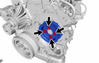
Remove the 4 bolts, No. 2 camshaft timing pulley flange and pump drive shaft pulley from the timing gear cover.
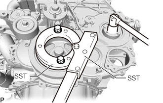
Using SST, hold the crankshaft pulley and remove the nut and O-ring.
- SST
- 09213-58014 (91551-80840)
09330-00021
13408
28.REMOVE CRANKSHAFT PULLEY SUB-ASSEMBLY
29.REMOVE TIMING GEAR COVER
13613E
30.REMOVE INJECTION GEAR
19315
31.REMOVE NO. 1 CRANKSHAFT POSITION SENSOR PLATE
13521
32.REMOVE CRANKSHAFT TIMING GEAR
13572
33.REMOVE IDLE GEAR THRUST PLATE
13525
34.REMOVE NO. 1 IDLE GEAR
13581
35.REMOVE NO. 1 IDLE GEAR SHAFT
22100
36.REMOVE FUEL SUPPLY PUMP ASSEMBLY
12101
37.REMOVE OIL PAN SUB-ASSEMBLY
15104
38.REMOVE OIL STRAINER SUB-ASSEMBLY
11320
39.REMOVE TIMING GEAR CASE ASSEMBLY