2GD-FTV COOLING RADIATOR INSTALLATION
PROCEDURE

 16400B
1.INSTALL RADIATOR DRAIN COCK PLUG
Install a new O-ring to the radiator drain cock plug.
Install the radiator drain cock plug to the radiator assembly.
16546
2.INSTALL RADIATOR PROTECTOR (w/o Air Conditioning System)
Attach the 2 guides and 2 claws to install the radiator protector to the radiator assembly.
16400
3.INSTALL RADIATOR ASSEMBLY
Temporarily install the radiator assembly to the vehicle.
w/ Air Conditioning System:
Attach the 2 guides and 2 claws to connect the cooler condenser assembly to the radiator assembly.
- NOTICE:
- ·
Do not apply any excessive force to the cooler condenser assembly and cooler pipe.
·Do not allow the radiator assembly to interfere with other parts.
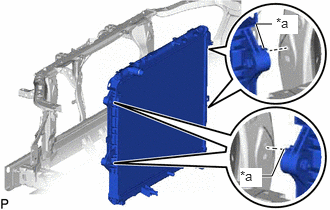
| *a | Claw |
Hook the claw of the radiator assembly as shown in the illustration.
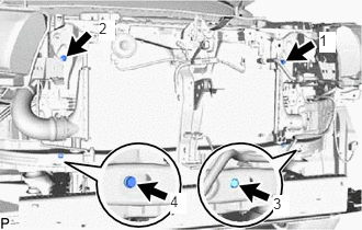
Install the radiator assembly with the 4 bolts in the order shown in the illustration.
- Torque:
- 22 N*m (224 kgf*cm, 16 ft.*lbf)
16572D
4.CONNECT NO. 2 RADIATOR HOSE
Connect the No. 2 radiator hose to the radiator assembly and slide the hose clamp to secure the hose.
16711
5.INSTALL FAN SHROUD
Install the fan pulley to the engine water pump assembly.
Place the fan shroud together with the fan with fluid coupling assembly between the engine and radiator assembly.
- NOTICE:
-
Do not allow the radiator assembly to interfere with other parts.
Temporarily install the fan with fluid coupling assembly to the engine water pump assembly with the 4 nuts.
- NOTICE:
- ·
Make sure to match the paint mark colors on the fan with fluid coupling assembly with the stud bolts of the same color on the engine water pump assembly.
·When installing the fan and generator V belt, make sure to securely tighten the nuts of the fan with fluid coupling assembly so that the fan pulley is properly aligned.
Attach the 2 guides and 2 claws to install the fan shroud to the radiator assembly.
Install the fan and generator V belt.
Click hereEngine / Hybrid System>2GD-FTV ENGINE MECHANICAL>DRIVE BELT>INSTALLATION
Tighten the 4 nuts holding the fan with fluid coupling assembly.
- Torque:
- 23 N*m (235 kgf*cm, 17 ft.*lbf)
Attach the 2 wire harness clamps.
32941
6.CONNECT NO. 1 OIL COOLER INLET HOSE (for Automatic Transmission)
Connect the No. 1 oil cooler inlet hose to the radiator assembly and slide the hose clamp to secure the hose.
Attach the clamp to connect the No. 1 oil cooler inlet hose to the fan shroud.
32942
7.CONNECT NO. 1 OIL COOLER OUTLET HOSE (for Automatic Transmission)
Connect the No. 1 oil cooler outlet tube to the radiator assembly and slide the hose clamp to secure the hose.
88359
8.INSTALL VISCOUS HEATER V BELT (w/ Viscous Heater)
16470
9.INSTALL RADIATOR RESERVOIR
Install the radiator reservoir with the 2 bolts.
- Torque:
- 5.0 N*m (51 kgf*cm, 44 in.*lbf)
Connect the water by-pass hose to the radiator assembly and slide the hose clamp to secure the hose.
Connect the No. 2 water by-pass hose to the radiator assembly and slide the hose clamp to secure the hose.
Attach the clamp to connect the No. 2 water by-pass hose to the fan shroud.
44369A
10.INSTALL NO. 1 OIL RESERVOIR BRACKET
Temporarily install the No. 1 oil reservoir bracket with the 3 bolts and tighten the 3 bolts.
- Torque:
- 4.5 N*m (46 kgf*cm, 40 in.*lbf)
44360
11.CONNECT VANE PUMP OIL RESERVOIR ASSEMBLY
Attach the claw to connect the vane pump oil reservoir assembly to the vane pump oil reservoir bracket.
Attach the clamp to connect the pressure feed tube assembly to the fan shroud.
16571C
12.INSTALL NO. 1 RADIATOR HOSE
Install the No. 1 radiator hose and slide the 2 hose clamps to secure the hose.
17362B
13.INSTALL NO. 2 AIR TUBE
Install the No. 2 air tube with the 2 bolts and tighten the hose clamp to secure the tube.
- Torque:
- for bolt : 8.0 N*m (82 kgf*cm, 71 in.*lbf)
- for hose clamp : 6.5 N*m (66 kgf*cm, 58 in.*lbf)
Attach the 4 clamps to connect the oil return hose to the No. 2 air tube.
17344E
14.INSTALL NO. 4 AIR HOSE
Install the No. 4 air hose and tighten the 2 hose clamps to secure the hose.
- Torque:
- 6.5 N*m (66 kgf*cm, 58 in.*lbf)
Attach the 2 clamps to connect the oil return hose to the No. 4 air hose.
15.ADD ENGINE COOLANT
16.INSPECT FOR COOLANT LEAK
16593
17.INSTALL NO. 1 RADIATOR AIR GUIDE
Install the No. 1 radiator air guide with 4 new clips.
51410
18.INSTALL NO. 1 ENGINE UNDER COVER ASSEMBLY (for 4WD and Pre-Runner)
53293C
19.INSTALL RADIATOR SIDE DEFLECTOR
for Steel Type Bumper:
Click hereVehicle Exterior>EXTERIOR PANELS / TRIM>FRONT BUMPER(for Steel Type Bumper)>INSTALLATION
for Resin Type Bumper:
Click hereVehicle Exterior>EXTERIOR PANELS / TRIM>FRONT BUMPER(for Resin Type Bumper)>INSTALLATION
12601B
20.INSTALL NO. 1 ENGINE COVER SUB-ASSEMBLY