STEERING COLUMN STEERING COLUMN ASSEMBLY INSTALLATION
PROCEDURE

 45250
1.INSTALL STEERING COLUMN ASSEMBLY
Install the steering column assembly with the 2 nuts and bolt.
- Torque:
- 36 N*m (367 kgf*cm, 27 ft.*lbf)
Connect the connectors and attach the wire harness clamps.
45025D
2.INSTALL NO. 1 STEERING COLUMN HOLE COVER SUB-ASSEMBLY
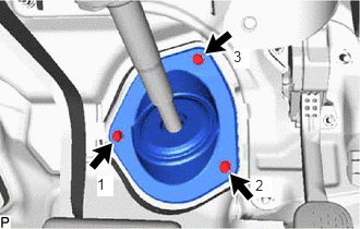
Install the steering column hole cover sub-assembly with the 3 bolts.
- Torque:
- 5.0 N*m (51 kgf*cm, 44 in.*lbf)
- HINT:
-
Install the bolts in the order shown in the illustration.
45219
3.CONNECT STEERING SLIDING YOKE
73900
4.INSTALL LOWER NO. 1 INSTRUMENT PANEL AIRBAG ASSEMBLY
5.INSTALL COMBINATION SWITCH ASSEMBLY WITH SPIRAL CABLE SUB-ASSEMBLY
Attach the 3 claws to install the combination switch assembly with spiral cable sub-assembly to the steering column sub-assembly.
Connect the connectors to the combination switch assembly with spiral cable sub-assembly to the spiral cable assembly.
45286B
6.INSTALL STEERING COLUMN UPPER COVER
Attach the 2 claws and 2 guides to install the steering column upper cover.
45287
7.INSTALL STEERING COLUMN LOWER COVER
Attach the 2 claws and 6 guides to install the steering column lower cover.
Install the 3 screws.
45100
8.INSTALL STEERING WHEEL ASSEMBLY
9.PLACE FRONT WHEELS FACING STRAIGHT AHEAD
28800
10.CONNECT CABLE TO NEGATIVE BATTERY TERMINAL
- NOTICE:
-
When disconnecting the cable, some systems need to be initialized after the cable is reconnected.
-
Click hereGeneral>INTRODUCTION>REPAIR INSTRUCTION>INITIALIZATION
11.CHECK SRS WARNING LIGHT
for Type A: Click hereVehicle Interior>SUPPLEMENTAL RESTRAINT SYSTEMS>AIRBAG SYSTEM(for Type A)>DIAGNOSIS SYSTEM
for Type B: Click hereVehicle Interior>SUPPLEMENTAL RESTRAINT SYSTEMS>AIRBAG SYSTEM(for Type B)>DIAGNOSIS SYSTEM
for Type C: Click hereVehicle Interior>SUPPLEMENTAL RESTRAINT SYSTEMS>AIRBAG SYSTEM(for Type C)>DIAGNOSIS SYSTEM