SEAT BELT FRONT SEAT OUTER BELT ASSEMBLY(for Double Cab) INSTALLATION
CAUTION / NOTICE / HINT
- HINT:
- ·
Use the same procedure for the RH and LH sides.
·The procedure listed below is for the LH side.
·A bolt without a torque specification is shown in the standard bolt chart.
Click hereGeneral>SPECIFICATIONS>STANDARD BOLT>SPECIFIED TORQUE FOR STANDARD BOLTS
PROCEDURE

 73200A
1.INSTALL FRONT SHOULDER BELT ANCHOR ADJUSTER ASSEMBLY
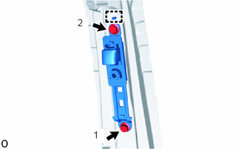
Attach the guide and temporarily install the front shoulder belt anchor adjuster assembly with the 2 bolts.
Tighten the 2 bolts in the order shown in the illustration.
- Torque:
- 42 N*m (428 kgf*cm, 31 ft.*lbf)
73136A
2.INSTALL SHOULDER BELT ANCHOR COVER LH
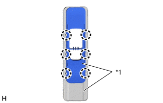
| *1 | Shoulder Belt Anchor Cover LH |
Attach the claw and install the 2 shoulder belt anchor cover LH.
73024
3.INSTALL FRONT SHOULDER BELT ANCHOR PLATE SUB-ASSEMBLY LH
- HINT:
-
Perform this procedure when replacing the shoulder belt anchor cover LH.
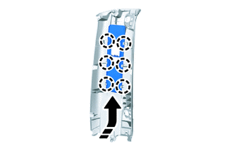

|
Install in this Direction |
Attach the claw and install the front shoulder belt anchor plate sub-assembly LH as shown in the illustration.
62412B
4.INSTALL UPPER CENTER PILLAR GARNISH LH
73220
5.INSTALL FRONT SEAT OUTER BELT ASSEMBLY LH
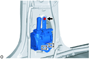
w/ Pretensioner:
Attach the 2 guides and install the front seat outer belt assembly LH with the bolt.
- Torque:
- 12.5 N*m (127 kgf*cm, 9 ft.*lbf)
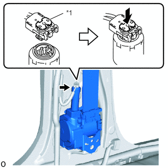
| *1 | Locking Button |
Connect the pretensioner connector and lock the locking button as shown in the illustration.
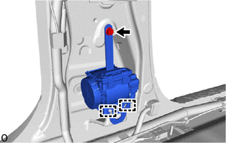
w/o Pretensioner:
Attach the 2 guides and install the front seat outer belt assembly LH with the bolt.
- Torque:
- 12.5 N*m (127 kgf*cm, 9 ft.*lbf)
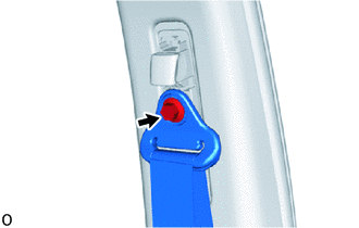
Connect the shoulder anchor of the front seat outer belt assembly LH with the bolt.
- Torque:
- 42 N*m (428 kgf*cm, 31 ft.*lbf)
Check that the ELR locks.
- NOTICE:
-
The check should be performed with the front seat outer belt assembly LH installed.
With the belt assembly installed, check that the belt locks when it is pulled out quickly.
73178A
6.INSTALL SEAT BELT ANCHOR COVER CAP
74680
7.INSTALL PILLAR ASSIST GRIP ASSEMBLY
62414A
8.INSTALL LOWER CENTER PILLAR GARNISH LH
73220
9.INSTALL FRONT SEAT OUTER BELT ASSEMBLY LH (Floor Anchor)
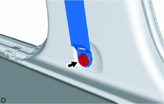
Connect the floor anchor of the front seat outer belt assembly LH with the bolt.
- Torque:
- 42 N*m (428 kgf*cm, 31 ft.*lbf)
67918E
10.INSTALL REAR DOOR SCUFF PLATE LH
67914B
11.INSTALL FRONT DOOR SCUFF PLATE LH
12.CONNECT CABLE TO NEGATIVE BATTERY TERMINAL
- NOTICE:
-
When disconnecting the cable, some systems need to be initialized after the cable is reconnected.
-
Click hereGeneral>INTRODUCTION>REPAIR INSTRUCTION>INITIALIZATION
13.CHECK SRS WARNING LIGHT