Home › Engine / Hybrid System › CRUISE CONTROL › CRUISE CONTROL SYSTEM › 2015.06–2016.07
RM33J0E _51 Engine / Hybrid System _038462 CRUISE CONTROL _0181542 CRUISE CONTROL SYSTEM C

CRUISE CONTROL  CRUISE CONTROL SYSTEM  P0571  Brake Switch "A" Circuit  


DESCRIPTION

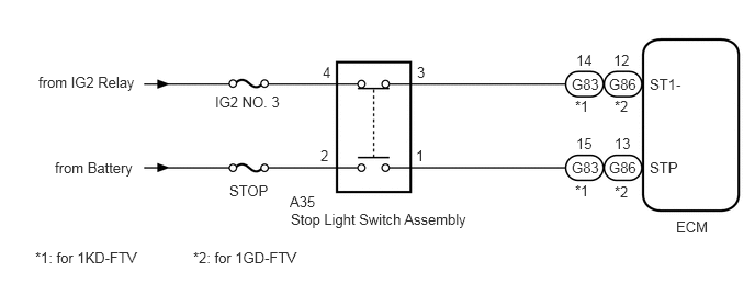
When the brake pedal is depressed, the stop light switch assembly sends a signal to the ECM. Upon receiving the signal, the ECM cancels the cruise control system.

DTC No. Detection Item DTC Detection Condition Trouble Area
P0571 Brake Switch "A" Circuit When voltage of STP terminal and that of ST1- terminal of ECM are less than 1 V for 0.5 seconds or more
·

Stop light switch assembly

·

ECM

·

Harness or connector


WIRING DIAGRAM

C337657E01
0.365,0.698 1.458,0.917 1.094,0.219 10 false from IG2 Relay 0.521,1.51 1.438,1.76 0.917,0.25 10 false from Battery 2.042,0.885 2.781,1.146 0.74,0.26 10 false IG2 NO. 3 2.177,1.729 2.594,1.979 0.417,0.25 10 false STOP 3.063,0.604 3.302,0.781 0.24,0.177 10 false 4 3.948,1.396 4.198,1.573 0.25,0.177 10 false 1 3.042,1.396 3.208,1.563 0.167,0.167 10 false 2 3.958,0.604 4.208,0.771 0.25,0.167 10 false 3 2.75,1.833 3.083,2.083 0.333,0.25 10 false A35 5.833,1.74 6.083,1.99 0.25,0.25 10 false *2 5.458,1.729 5.708,1.896 0.25,0.167 10 false *1 5.427,1.51 5.844,1.688 0.417,0.177 10 false G83 5.781,1.51 6.198,1.771 0.417,0.26 10 false G86 5.823,0.49 6.156,0.667 0.333,0.177 10 false 12 5.469,1.281 5.719,1.448 0.25,0.167 10 false 15 5.458,0.927 5.708,1.177 0.25,0.25 10 false *1 5.427,0.719 5.844,0.896 0.417,0.177 10 false G83 5.469,0.49 5.719,0.656 0.25,0.167 10 false 14 5.833,1.281 6.073,1.448 0.24,0.167 10 false 13 5.781,0.719 6.188,0.885 0.406,0.167 10 false G86 5.833,0.927 6.073,1.177 0.24,0.25 10 false *2 6.167,0.719 6.583,0.969 0.417,0.25 10 false ST1- 6.167,1.51 6.583,1.76 0.417,0.25 10 false STP 6.417,2.073 6.917,2.25 0.5,0.177 10 false ECM 2.76,2 4.583,2.26 1.823,0.26 10 false Stop Light Switch Assembly 0.333,2.365 1.521,2.594 1.188,0.229 10 false *1: for 1KD-FTV 1.833,2.365 2.833,2.563 1,0.198 10 false *2: for 1GD-FTV

CAUTION / NOTICE / HINT

NOTICE:

Inspect the fuses for circuits related to this system before performing the following procedure.


PROCEDURE
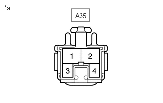
1.CHECK HARNESS AND CONNECTOR (STOP LIGHT SWITCH ASSEMBLY - BATTERY)
a.
E270489C06
1.5,0.188 1.896,0.448 0.396,0.26 0.094,0.083 0.406,0.281 0.313,0.198 10 false *a 1.583,0.25 2.042,0.448 0.458,0.198 10 false A35
*a Front view of wire harness connector
(to Stop Light Switch Assembly)


Disconnect the stop light switch assembly connector.


b.

Measure the voltage according to the value(s) in the table below.

Standard Voltage:
Tester Connection Condition Specified Condition
A35-2 - Body ground Always 11 to 14 V
A35-4 - Body ground Ignition switch ON 11 to 14 V
A35-4 - Body ground Ignition switch off Below 1 V


Result:
Proceed to
OK
NG


OK

2.INSPECT STOP LIGHT SWITCH ASSEMBLY

NG

REPAIR OR REPLACE HARNESS OR CONNECTOR

2.INSPECT STOP LIGHT SWITCH ASSEMBLY
a.

Remove the stop light switch assembly.

Click hereVehicle Exterior>LIGHTING (EXT)>STOP LIGHT SWITCH>REMOVAL


b.

Inspect the stop light switch assembly.

Click hereVehicle Exterior>LIGHTING (EXT)>STOP LIGHT SWITCH>INSPECTION


Result:
Proceed to
OK
NG


OK

3.CHECK HARNESS AND CONNECTOR (ECM - STOP LIGHT SWITCH ASSEMBLY)

NG

REPLACE STOP LIGHT SWITCH ASSEMBLY

3.CHECK HARNESS AND CONNECTOR (ECM - STOP LIGHT SWITCH ASSEMBLY)
a.

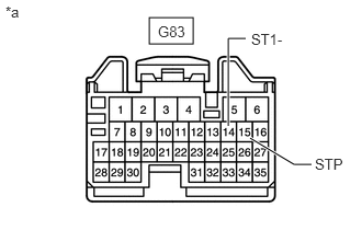
for 1KD-FTV

i.
C330986C01
1.417,0.167 1.833,0.417 0.417,0.25 2.167,1.198 2.167,0.365 2.167,0.365 2.333,0.365 true 2.375,1.313 2.792,1.563 2.792,1.563 2.958,1.563 true 1.5,0.219 1.958,0.417 0.458,0.198 10 false G83 2.385,0.292 2.833,0.49 0.448,0.198 10 false ST1- 2.99,1.479 3.344,1.677 0.354,0.198 10 false STP 0.052,0.031 0.365,0.229 0.313,0.198 10 false *a
*a Front view of wire harness connector
(to ECM)


Disconnect the ECM connector.


ii.

Measure the voltage according to the value(s) in the table below.

Standard Voltage:
Tester Connection Condition Specified Condition
G83-14 (ST1-) - Body ground Ignition switch ON, brake pedal depressed 0 to 1.5 V
Ignition switch ON, brake pedal released 7.5 to 14 V
G83-15 (STP) - Body ground Brake pedal depressed 7.5 to 14 V
Brake pedal released 0 to 1.5 V


b.

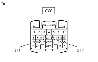
for 1GD-FTV

i.
C326505C05
1.5,0.26 1.917,0.5 0.417,0.24 1.635,1.354 0.667,1.667 true 2.75,1.667 1.792,1.354 true 0.052,0.042 0.365,0.24 0.313,0.198 10 false *a 1.583,0.302 2.042,0.5 0.458,0.198 10 false G86 0.469,1.698 1.083,1.896 0.615,0.198 10 false ST1- 2.688,1.688 3.146,1.885 0.458,0.198 10 false STP
*a Front view of wire harness connector
(to ECM)


Disconnect the ECM connector.


ii.

Measure the voltage according to the value(s) in the table below.

Standard Voltage:
Tester Connection Condition Specified Condition
G86-12 (ST1-) - Body ground Ignition switch ON, brake pedal depressed 0 to 1.5 V
Ignition switch ON, brake pedal released 7.5 to 14 V
G86-13 (STP) - Body ground Brake pedal depressed 7.5 to 14 V
Brake pedal released 0 to 1.5 V


Result:
Proceed to
OK
NG


OK

NG

REPAIR OR REPLACE HARNESS OR CONNECTOR