DOOR / HATCH REAR DOOR(for Smart Cab) REASSEMBLY
CAUTION / NOTICE / HINT
- HINT:
- ·
Use the same procedure for the RH and LH sides.
·The procedure listed below is for the LH side.
·A bolt without a torque specification is shown in the standard bolt chart.
Click hereGeneral>SPECIFICATIONS>STANDARD BOLT>SPECIFIED TORQUE FOR STANDARD BOLTS
PROCEDURE

 67003C
1.INSTALL REAR DOOR PANEL CUSHION
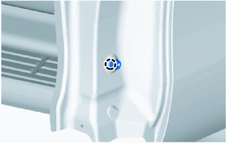
Attach the claw to install a new rear door panel cushion.
67897H
2.INSTALL REAR DOOR CUSHION
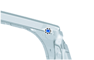
Attach the claw to install a new rear door cushion.
67837C
3.INSTALL REAR DOOR DUST PROOF SEAL
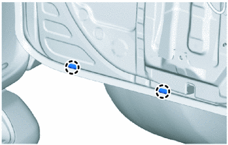
Attach the claw to install 2 new rear door dust proof seals.
67872F
4.INSTALL ACCESS PANEL WEATHERSTRIP LH
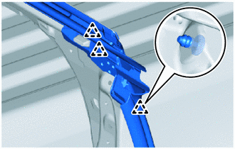
Attach the clip.
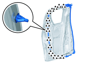
Attach the clip.
Attach the clip and remove the peeling paper from double-sided tape and press the double-sided tape to the rear side of the access door panel.
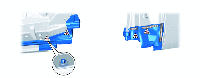

|
Double-sided Tape | - | - |
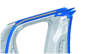
|
|
Double-sided Tape |
Remove the peeling paper from double-sided tape and press the double-sided tape to the upper side of the access door panel.
Remove the peeling paper from double-sided tape and press the double-sided tape to the corner of the access door panel.
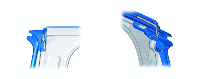
|
|
Double-sided Tape | - | - |
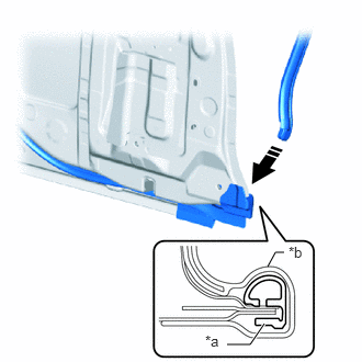
| *a | Mold Portion |
| *b | Lower Corner Portion |

|
Install in this Direction |
Insert the mold portion to the lower corner portion to install a new access panel weatherstrip LH.
68640E
5.INSTALL ACCESS PANEL CHECK ASSEMBLY LH
Apply MP grease to the sliding area of the access panel check assembly LH.
When reusing a bolt:
Clean the threads of the bolt (B) with non-residue solvent.
Apply adhesive to the threads of the bolt (B).
- Adhesive:
Toyota Genuine Adhesive 1324, Three Bond 1324 or equivalent.
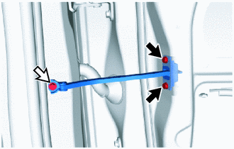

|
Bolt (A) |

|
Bolt (B) |
Install the access panel check assembly LH with the 2 bolts (A) and bolt (B).
- Torque:
- Bolt (A) : 8.0 N*m (82 kgf*cm, 71 in.*lbf)
- Bolt (B) : 30 N*m (306 kgf*cm, 22 ft.*lbf)
69410D
6.INSTALL ACCESS PANEL LOCK STRIKER PLATE ASSEMBLY
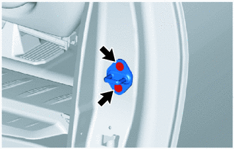
Using a T40 "TORX" socket wrench, install the access panel lock striker plate assembly with the 2 screws
- Torque:
- 23 N*m (235 kgf*cm, 17 ft.*lbf)
84233
7.INSTALL FRONT DOOR COURTESY LIGHT SWITCH ASSEMBLY
69780C
8.INSTALL ACCESS PANEL LOCK CANCEL LEVER ASSEMBLY LH
Apply MP grease to the rotating and sliding areas of the access panel lock cancel lever assembly LH.
When reusing a screw:
Clean the threads of the screw with non-residue solvent.
Apply adhesive to the threads of the screw.
- Adhesive:
Toyota Genuine Adhesive 1324, Three Bond 1324 or equivalent.
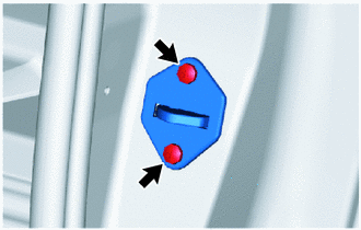
Install the access panel lock cancel lever assembly LH with the 2 screws.
- Torque:
- 5.0 N*m (51 kgf*cm, 44 in.*lbf)
62742
9.INSTALL QUARTER WINDOW WEATHERSTRIP LH
Remove any non-drying sealer on the body with non-residue solvent.
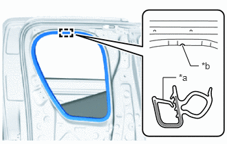
| *a | Paint Mark |
| *b | Mark Position |
Align the paint mark with the position on the access panel LH flange and install a new quarter window weatherstrip LH.
- NOTICE:
- ·
Always align the paint mark when installing the part. If the paint mark position is out of place, coolant leaks may occur.
·After the installation, check that the corners are properly installed.
- HINT:
-
To easily install the weatherstrip, first install the area with the paint mark as shown in the illustration. Then install the part toward the corners and push any excess length into the corners.
68114
10.INSTALL QUARTER WINDOW GLASS LH
69640D
11.INSTALL ACCESS PANEL LOCK REMOTE CONTROL ASSEMBLY LH
Apply MP grease to the rotating and sliding areas of the access panel lock remote control assembly LH.
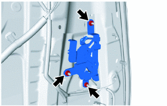
Install the access panel lock remote control assembly LH with the 3 nuts.
69390D
12.INSTALL LOWER ACCESS PANEL LOCK ASSEMBLY LH
69360L
13.INSTALL UPPER ACCESS PANEL LOCK ASSEMBLY LH
69208K
14.INSTALL ACCESS PANEL INSIDE HANDLE SUB-ASSEMBLY LH
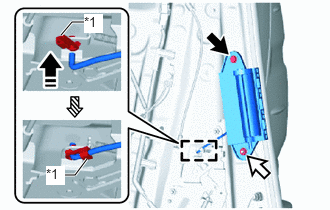
| *1 | Snap |
|
|
Bolt |
|
|
Nut |

|
Order of Installation |
|
|
Install in this Direction |
Install the nut, bolt and access panel inside handle sub-assembly LH.
Attach the snap as shown in the illustration.
86160B
15.INSTALL REAR SPEAKER ASSEMBLY
16.INSTALL SCREW GROMMET
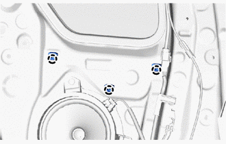
Attach the claw to install 3 new screw grommets.
67674A
17.INSTALL REAR DOOR FRAME GARNISH LH
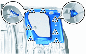
Attach the clip to install the rear door frame garnish LH.
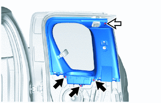
|
|
Screw |
|
|
Clip |
Install the clip and 3 screws.
73220
18.INSTALL FRONT SEAT OUTER BELT ASSEMBLY LH
73178A
19.INSTALL SEAT BELT ANCHOR COVER CAP
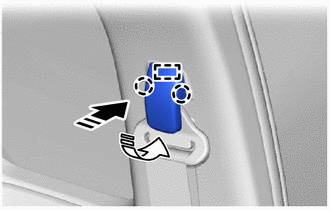
|
|
Install in this Direction (1) |

|
Install in this Direction (2) |
Attach the guide and claw to install the seat belt anchor cover cap as shown in the illustration.
67604
20.INSTALL REAR DOOR TRIM BOARD SUB-ASSEMBLY LH
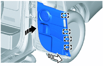
|
|
Install in this Direction (1) |
|
|
Install in this Direction (2) |
Attach the guide as shown in the illustration.
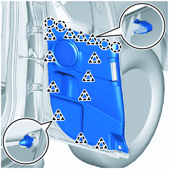
Attach the claw and clip to install the rear door trim board sub-assembly LH.
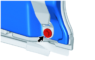
Connect the front seat outer belt floor anchor with the bolt.
73233
21.INSTALL LAP BELT OUTER ANCHOR COVER
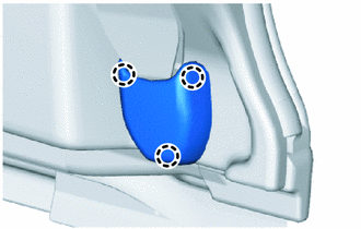
Attach the claw to install the lap belt outer anchor cover.
22.CONNECT CABLE TO NEGATIVE BATTERY TERMINAL
- NOTICE:
-
When disconnecting the cable, some systems need to be initialized after the cable is reconnected.
-
Click hereGeneral>INTRODUCTION>REPAIR INSTRUCTION>INITIALIZATION
23.CHECK SRS WARNING LIGHT
for Type A:
Click hereVehicle Interior>SUPPLEMENTAL RESTRAINT SYSTEMS>AIRBAG SYSTEM(for Type A)>DIAGNOSIS SYSTEM
for Type B:
Click hereVehicle Interior>SUPPLEMENTAL RESTRAINT SYSTEMS>AIRBAG SYSTEM(for Type B)>DIAGNOSIS SYSTEM