AXLE AND DIFFERENTIAL STEERING KNUCKLE(for 4WD and Pre-Runner) INSTALLATION
CAUTION / NOTICE / HINT
- HINT:
- ·
Use the same procedure for the RH and LH sides.
·The procedure listed below is for the LH side.
PROCEDURE

 43212
1.INSTALL STEERING KNUCKLE LH
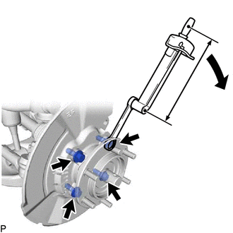
Apply MP grease to a new O-ring.
Install the O-ring to the front axle hub sub-assembly LH.
Install the dust cover and front axle hub sub-assembly LH to the steering knuckle LH with the 4 bolts.
- Torque:
- Specified tightening torque : 80 N*m (816 kgf*cm, 59 ft.*lbf)
- HINT:
- ·
Calculate the torque wrench reading when changing the fulcrum length of the torque wrench.
Click hereGeneral>INTRODUCTION>REPAIR INSTRUCTION>PRECAUTION
·When using a ball joint lock nut wrench (fulcrum length of 149 mm (5.866 in.)) + torque wrench (fulcrum length of 380 mm (14.961 in.)): 57.5 N*m (586 kgf*cm, 42 ft.*lbf).
43502K
2.INSTALL FRONT AXLE HUB DUST SEAL (for 4WD)
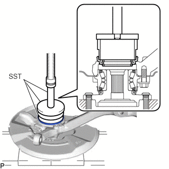
Using SST and a press, press in a new front axle hub dust seal.
- SST
- 09527-17011
09950-70010 (09951-07100)
09951-01000
43442B
3.INSTALL KNUCKLE GREASE RETAINER CAP LH (for Pre-Runner)
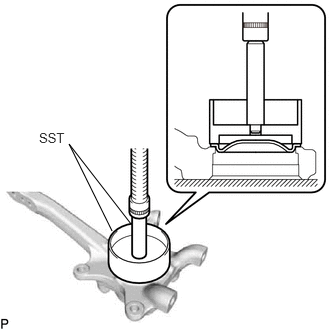
Using SST and a press, press in a new knuckle retainer cap LH.
- SST
- 09950-70010 (09951-07100)
09608-36010
48630
4.CONNECT FRONT UPPER SUSPENSION ARM ASSEMBLY LH
Install the front upper suspension arm assembly LH to the steering knuckle LH with a new nut.
- Torque:
- 110 N*m (1122 kgf*cm, 81 ft.*lbf)
Install a new clip.
- NOTICE:
-
If the holes for the clip are not aligned, tighten the nut an additional 60°.
48069
5.CONNECT FRONT LOWER NO. 1 SUSPENSION ARM ASSEMBLY LH
Connect the front lower No. 1 suspension arm assembly LH to the steering knuckle LH with the 2 bolts.
- Torque:
- 160 N*m (1632 kgf*cm, 118 ft.*lbf)
6.CONNECT TIE ROD END SUB-ASSEMBLY LH
48810
7.CONNECT FRONT STABILIZER LINK ASSEMBLY LH
Connect the front stabilizer link assembly LH to the steering knuckle LH with the nut.
- Torque:
- 70 N*m (714 kgf*cm, 52 ft.*lbf)
- HINT:
-
If the ball joint turns together with the nut, use a 6 mm hexagon wrench to hold the stud.
43502H
8.INSTALL FRONT AXLE SHAFT NUT LH (for 4WD)
43514C
9.INSTALL FRONT AXLE HUB GREASE CAP LH (for 4WD)
43512
10.INSTALL FRONT DISC
47750
11.INSTALL FRONT DISC BRAKE CYLINDER ASSEMBLY LH
89543
12.CONNECT FRONT SPEED SENSOR LH
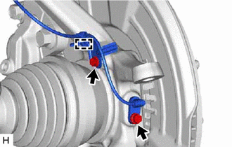
Install the skid control sensor clamp to the steering knuckle with the bolt.
- Torque:
- 13.5 N*m (138 kgf*cm, 10 ft.*lbf)
Install the speed sensor to the steering knuckle with the bolt.
- Torque:
- 8.5 N*m (87 kgf*cm, 75 in.*lbf)
- NOTICE:
- ·
Make sure there are no pieces of iron or other foreign matter attached to the sensor tip.
·While inserting the speed sensor into the knuckle hole, do not strike or damage the sensor tip.
·After installing the speed sensor, make sure there is no clearance or foreign matter between the sensor stay part and the knuckle.
·When installing the sensor, do not twist the wire harness.
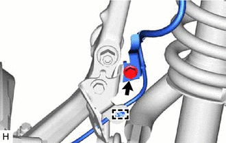
Install the harness clamp with the bolt.
- Torque:
- 32 N*m (326 kgf*cm, 24 ft.*lbf)
- NOTICE:
- ·
When installing the clamp, do not twist the wire harness.
·Make sure the clamp rotation stopper touches the installation position.
Attach the clamp.
13.INSTALL FRONT WHEEL
14.INSPECT AND ADJUST FRONT WHEEL ALIGNMENT
15.CHECK ABS SPEED SENSOR SIGNAL
16.PERFORM INITIALIZATION (w/ Automatic Headlight Beam Level Control System)
17.INSPECT AUTOMATIC LIGHT CONTROL SYSTEM (w/ Automatic Headlight Beam Level Control System)
18.INSPECT HEADLIGHT AIMING (w/ Automatic Headlight Beam Level Control System)