BRAKE CONTROL / DYNAMIC CONTROL SYSTEMS ANTI-LOCK BRAKE SYSTEM TC and CG Terminal Circuit
DESCRIPTION
Connecting terminals TC and CG of the DLC3 causes the ECU to display the DTC by blinking the ABS warning light.
WIRING DIAGRAM
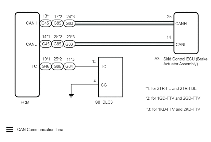
CAUTION / NOTICE / HINT
- NOTICE:
-
When replacing the skid control ECU (brake actuator assembly), perform Test Mode (Signal Check) to acquire the rear differential lock identification information.
-
Click hereBrake>BRAKE CONTROL / DYNAMIC CONTROL SYSTEMS>ANTI-LOCK BRAKE SYSTEM>TEST MODE PROCEDURE
PROCEDURE
Check if CAN communication system DTCs are output.
for LHD: Click herePower Source / Network>NETWORKING>CAN COMMUNICATION SYSTEM(for LHD)>DIAGNOSIS SYSTEM
for RHD: Click herePower Source / Network>NETWORKING>CAN COMMUNICATION SYSTEM(for RHD)>DIAGNOSIS SYSTEM
- Result:
Proceed to DTC is not output DTC is output
DTC is not output
DTC is output
for LHD: Click herePower Source / Network>NETWORKING>CAN COMMUNICATION SYSTEM(for LHD)>HOW TO PROCEED WITH TROUBLESHOOTING
for RHD: Click herePower Source / Network>NETWORKING>CAN COMMUNICATION SYSTEM(for RHD)>HOW TO PROCEED WITH TROUBLESHOOTING
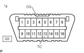
| *a | Front view of DLC3 |
Turn the ignition switch to ON.
Measure the voltage according to the value(s) in the table below.
- Standard Voltage:
Tester Connection Switch Condition Specified Condition G8-13 (TC) - G8-4 (CG) Ignition switch ON 11 to 14 V
- Result:
Proceed to OK NG
OK
NG
| *a | Front view of DLC3 |
Turn the ignition switch off.
Replace the ECM.
for 1GD-FTV: Click hereEngine / Hybrid System>1GD-FTV ENGINE CONTROL>ECM>REMOVAL
for 1KD-FTV: Click hereEngine / Hybrid System>1KD-FTV ENGINE CONTROL>ECM>REMOVAL
for 2GD-FTV: Click hereEngine / Hybrid System>2GD-FTV ENGINE CONTROL>ECM>REMOVAL
for 2KD-FTV: Click hereEngine / Hybrid System>2KD-FTV ENGINE CONTROL>ECM>REMOVAL
for 2TR-FE: Click hereEngine / Hybrid System>2TR-FE ENGINE CONTROL>ECM>REMOVAL
for 2TR-FBE: Click hereEngine / Hybrid System>2TR-FBE ENGINE CONTROL>ECM>REMOVAL
Using SST, connect terminals 13 (TC) and 4 (CG) of the DLC3.
- SST
- 09843-18040
Check that the ABS warning light are blinking.
- OK:
The ABS warning light are blinking.
- Result:
Proceed to OK NG
OK
NG
Turn the ignition switch off.
Disconnect the G46*1, G85*2 or G84*3 ECM connector.
*1: for 2TR-FE and 2TR-FBE
*2: for 1GD-FTV and 2GD-FTV
*3: for 1KD-FTV and 2KD-FTV
Measure the resistance according to the value(s) in the table below.
- Standard Resistance:
for 2TR-FE and 2TR-FBE: Tester Connection Condition Specified Condition G8-13 (TC) - G46-19 (TC) Always Below 1 Ω G8-13 (TC) or G46-19 (TC) - Body ground Always 10 kΩ or higher
for 1GD-FTV and 2GD-FTV: Tester Connection Condition Specified Condition G8-13 (TC) - G85-25 (TC) Always Below 1 Ω G8-13 (TC) or G85-25 (TC) - Body ground Always 10 kΩ or higher
for 1KD-FTV and 2KD-FTV: Tester Connection Condition Specified Condition G8-13 (TC) - G84-11 (TC) Always Below 1 Ω G8-13 (TC) or G84-11 (TC) - Body ground Always 10 kΩ or higher
- Result:
Proceed to OK NG
OK
NG
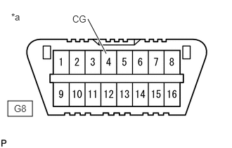
| *a | Front view of DLC3 |
Measure the resistance according to the value(s) in the table below.
- Standard Resistance:
Tester Connection Condition Specified Condition G8-4 (CG) - Body ground Always Below 1 Ω
- Result:
Proceed to OK NG
OK
NG
| *a | Front view of DLC3 |
Replace the ECM.
for 1GD-FTV: Click hereEngine / Hybrid System>1GD-FTV ENGINE CONTROL>ECM>REMOVAL
for 1KD-FTV: Click hereEngine / Hybrid System>1KD-FTV ENGINE CONTROL>ECM>REMOVAL
for 2GD-FTV: Click hereEngine / Hybrid System>2GD-FTV ENGINE CONTROL>ECM>REMOVAL
for 2KD-FTV: Click hereEngine / Hybrid System>2KD-FTV ENGINE CONTROL>ECM>REMOVAL
for 2TR-FE: Click hereEngine / Hybrid System>2TR-FE ENGINE CONTROL>ECM>REMOVAL
for 2TR-FBE: Click hereEngine / Hybrid System>2TR-FBE ENGINE CONTROL>ECM>REMOVAL
Using SST, connect terminals 13 (TC) and 4 (CG) of the DLC3.
- SST
- 09843-18040
Check that the ABS warning light are blinking.
- OK:
The ABS warning light are blinking.
- Result:
Proceed to OK NG
OK
NG