INTERIOR PANELS / TRIM UPPER INSTRUMENT PANEL INSTALLATION
CAUTION / NOTICE / HINT
- HINT:
-
A bolt without a torque specification is shown in the standard bolt chart.
-
Click hereGeneral>SPECIFICATIONS>STANDARD BOLT>SPECIFIED TORQUE FOR STANDARD BOLTS
PROCEDURE

 55302A
1.INSTALL UPPER INSTRUMENT PANEL SUB-ASSEMBLY
Attach the guide to install the upper instrument panel sub-assembly.
Attach the clip as shown in the illustration.
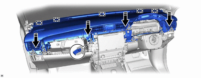

|
Install in this Direction | - | - |
Install the passenger airbag installation bolt <B>.
- Torque:
- 16 N*m (163 kgf*cm, 12 ft.*lbf)
Install the 2 clips <A>.
Connect the connector and attach the clamp.
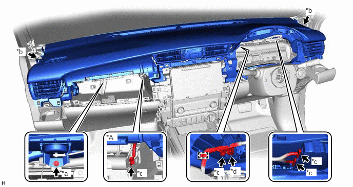
| *A | w/ Navigation System | - | - |
| *a | Passenger Airbag Installation Bolt <B> | *b | Clip <A> |
| *c | Connector | *d | Passenger Airbag Connector |
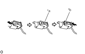
| *a | Lock Slider |
| *b | Lock Position |
Connect the passenger airbag connector.
- NOTICE:
-
When handling the passenger airbag connector, take care not to damage the airbag wire harness.
Check that the lock slider is in the lock position.
62212
2.INSTALL FRONT PILLAR GARNISH LH
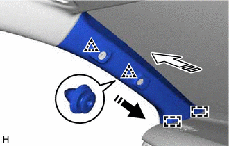
|
|
Install in this Direction (1) |

|
Install in this Direction (2) |
Attach the guide and clip to install the front pillar garnish LH as shown in the illustration.
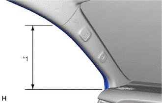
| *1 | Front Door Opening Trim Weatherstrip LH |
Connect the front door opening trim weatherstrip LH in the range shown in the illustration.
62211
3.INSTALL FRONT PILLAR GARNISH RH
|
|
Install in this Direction (1) |
|
|
Install in this Direction (2) |
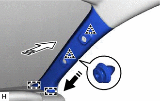
Attach the guide and clip to install the front pillar garnish RH as shown in the illustration.
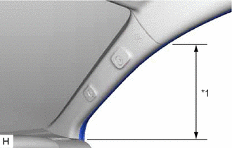
| *1 | Front Door Opening Trim Weatherstrip RH |
Connect the front door opening trim weatherstrip RH in the range shown in the illustration.
74603
4.INSTALL FRONT ASSIST GRIP SUB-ASSEMBLY
- HINT:
-
Use the same procedure for both front assist grip sub-assemblies.
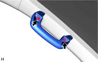
Install the front assist grip sub-assembly with the 2 bolts.
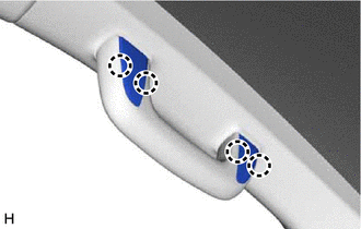
Attach the claw to close the assist grip covers.
55318C
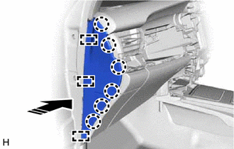
5.INSTALL INSTRUMENT SIDE PANEL LH
Connect the connector.
|
|
Install in this Direction |
Attach the guide and claw to install the instrument side panel LH as shown in the illustration.
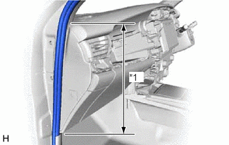
| *1 | Front Door Opening Trim Weatherstrip LH |
Connect the front door opening trim weatherstrip LH in the range shown in the illustration.
62112
6.INSTALL COWL SIDE TRIM BOARD LH
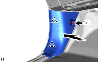
| *a | Cap Nut |
|
|
Install in this Direction |
Attach the clip to install the cowl side trim board LH as shown in the illustration.
Install the cap nut.
67914B
7.INSTALL FRONT DOOR SCUFF PLATE LH
55317A
8.INSTALL INSTRUMENT SIDE PANEL RH
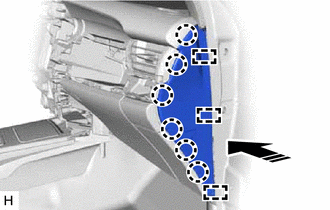
|
|
Install in this Direction |
Attach the guide and claw to install the instrument side panel RH as shown in the illustration.
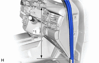
| *1 | Front Door Opening Trim Weatherstrip RH |
Connect the front door opening trim weatherstrip RH in the range shown in the illustration.
62111C
9.INSTALL COWL SIDE TRIM BOARD RH
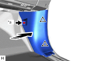
| *a | Cap Nut |
|
|
Install in this Direction |
Attach the clip to install the cowl side trim board RH as shown in the illustration.
Install the cap nut.
67913B
10.INSTALL FRONT DOOR SCUFF PLATE RH
55405B
11.INSTALL CENTER INSTRUMENT CLUSTER FINISH PANEL SUB-ASSEMBLY
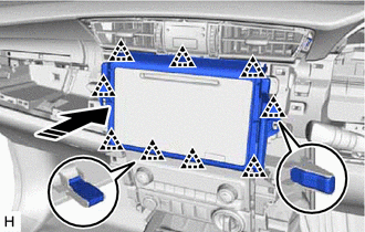
|
|
Install in this Direction |
Attach the clip to install the center instrument cluster finish panel sub-assembly as shown in the illustration.
55041B
12.INSTALL NO. 1 INSTRUMENT PANEL BOX DOOR SUB-ASSEMBLY
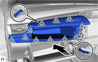
|
|
Install in this Direction |
Attach the clip to install the No. 1 instrument panel box door sub-assembly as shown in the illustration.
83100
13.INSTALL COMBINATION METER ASSEMBLY
55410C
14.INSTALL INSTRUMENT CLUSTER FINISH PANEL ASSEMBLY
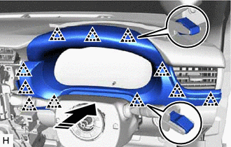
|
|
Install in this Direction |
Attach the clip to install the instrument cluster finish panel assembly as shown in the illustration.
55011A
15.INSTALL NO. 1 INSTRUMENT PANEL GARNISH SUB-ASSEMBLY
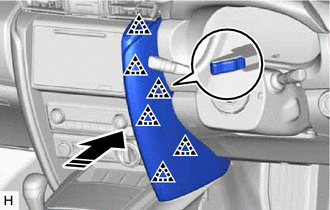
|
|
Install in this Direction |
Attach the clip to install the No. 1 instrument panel garnish sub-assembly as shown in the illustration.
55012A
16.INSTALL NO. 2 INSTRUMENT PANEL GARNISH SUB-ASSEMBLY
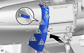
|
|
Install in this Direction |
Attach the clip to install the No. 2 instrument panel garnish sub-assembly as shown in the illustration.
55667
17.INSTALL INSTRUMENT PANEL REGISTER BEZEL GARNISH
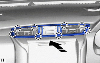
|
|
Install in this Direction |
Attach the claw to install the instrument panel register bezel garnish as shown in the illustration.
45100
18.INSTALL STEERING WHEEL ASSEMBLY
19.CONNECT CABLE TO NEGATIVE BATTERY TERMINAL
- NOTICE:
-
When disconnecting the cable, some systems need to be initialized after the cable is reconnected.
-
Click hereGeneral>INTRODUCTION>REPAIR INSTRUCTION>INITIALIZATION
20.CHECK SRS WARNING LIGHT