AXLE AND DIFFERENTIAL REAR DIFFERENTIAL LOCK CONTROL SWITCH REMOVAL
PROCEDURE

 1. PRECAUTION
- NOTICE:
-
After turning the engine switch off, waiting time may be required before disconnecting the cable from the battery terminal. Therefore, make sure to read the disconnecting the cable from the battery terminal notice before proceeding with work.
-
Click hereGeneral>INTRODUCTION>REPAIR INSTRUCTION>PRECAUTION
2.DISCONNECT CABLE FROM NEGATIVE BATTERY TERMINAL
- CAUTION:
-
Wait at least 90 seconds after disconnecting the cable from the negative (-) battery terminal to disable the SRS system.
- NOTICE:
-
When disconnecting the cable, some systems need to be initialized after the cable is reconnected.
-
Click hereGeneral>INTRODUCTION>REPAIR INSTRUCTION>INITIALIZATION
55667
3.REMOVE INSTRUMENT PANEL REGISTER BEZEL GARNISH
55011A
4.REMOVE NO. 1 INSTRUMENT PANEL GARNISH SUB-ASSEMBLY
55012A
5.REMOVE NO. 2 INSTRUMENT PANEL GARNISH SUB-ASSEMBLY
33504F
6.REMOVE SHIFT LEVER KNOB SUB-ASSEMBLY
58808
7.REMOVE SHIFTING HOLE COVER SUB-ASSEMBLY (for Automatic Transmission)
58804A
8.REMOVE UPPER CONSOLE PANEL SUB-ASSEMBLY
55405B
9.REMOVE CENTER INSTRUMENT CLUSTER FINISH PANEL SUB-ASSEMBLY
55407C
10.REMOVE LOWER INSTRUMENT COVER SUB-ASSEMBLY
84725A
11.REMOVE DIFFERENTIAL LOCK SWITCH
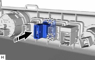

|
Remove in this Direction |
Disconnect the differential lock switch connector.
Detach the 2 claws and remove the differential lock switch from the lower instrument cover sub-assembly.