RC60 / RC61 MANUAL TRANSMISSION / TRANSAXLE MANUAL TRANSMISSION SYSTEM P0717 Input/Turbine Speed Sensor "A" Circuit No Signal P0806 Clutch Position Sensor Circuit Range/Performance P0811 Excessive Clutch Slippage
DESCRIPTION
| DTC No. | Detection Item | DTC Detection Condition | Trouble Area | Warning Indicate | Memory |
|---|---|---|---|---|---|
| P0717 | Input/Turbine Speed Sensor "A" Circuit No Signal | While driving after warm-up with clutch engaged, transmission input speed is not input
(1-trip detection logic) |
·
Harness and connector ·
Transmission revolution sensor ·
ECM |
Master Warning Light:
Comes on |
DTC stored |
| P0806 | Clutch Position Sensor Circuit Range/Performance | While driving after warm-up with clutch engaged, clutch stroke sensor value continuously indicates clutch disengaged
(1-trip detection logic) |
·
Harness and connector ·
Clutch stroke sensor ·
ECM |
Master Warning Light:
Comes on |
DTC stored |
| P0811 | Excessive Clutch Slippage | With clutch completely engaged, divergence between transmission input speed and engine speed is continuously greater than threshold
(1-trip detection logic) |
·
Harness and connector ·
Transmission revolution sensor ·
Clutch stroke sensor ·
Clutch slippage ·
ECM |
Master Warning Light:
Comes on |
DTC stored |
WIRING DIAGRAM
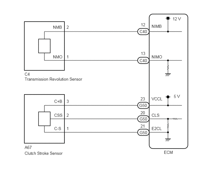
CAUTION / NOTICE / HINT
- NOTICE:
-
Perform registration and/or initialization when parts related to the iMT system are replaced.
-
Click hereDrivetrain>RC60 / RC61 MANUAL TRANSMISSION / TRANSAXLE>MANUAL TRANSMISSION SYSTEM>INITIALIZATION
- HINT:
-
After the repair, clear the DTCs and perform the following procedure to check that DTCs are not output.
- 1.
Perform the Road Test.
Click hereDrivetrain>RC60 / RC61 MANUAL TRANSMISSION / TRANSAXLE>MANUAL TRANSMISSION SYSTEM>ROAD TEST
2.Check for DTCs again.
Click hereDrivetrain>RC60 / RC61 MANUAL TRANSMISSION / TRANSAXLE>MANUAL TRANSMISSION SYSTEM>DTC CHECK / CLEAR
PROCEDURE
Connect the GTS to the DLC3.
Turn the ignition switch to ON.
Turn the GTS on.
Enter the following menus: Powertrain / Engine and ECT / Data List
According to the display on the GTS, read the Data List.
- Powertrain > Engine > Data List
-
Tester Display Measurement Item Range Normal Condition Diagnostic Note Engine Speed Engine speed Min.: 0 rpm
Max.: 16383 rpm710 to 810 rpm: Idling When the crankshaft position sensor is malfunctioning, "Engine Speed" is approximately 0 rpm or varies greatly from the actual engine speed. SPD (NIM) Input shaft speed (NIM) Min.: 0 rpm
Max.: 16383 rpmInput shaft speed (NIM) equal to engine speed (NE): Clutch pedal not depressed, vehicle running -
- Powertrain > Engine > Data List
-
Tester Display Engine Speed SPD (NIM) - 50003 234 9,1119
- OK:
When the clutch is engaged, the engine speed is constant and the difference between "Engine Speed" and "SPD (NIM)" in the Data List is below 200 rpm.
- Result:
Proceed to OK NG
OK
NG
Connect the GTS to the DLC3.
Turn the ignition switch to ON.
Turn the GTS on.
Enter the following menus: Powertrain / Engine and ECT / Data List
According to the display on the GTS, read the Data List.
- Powertrain > Engine > Data List
-
Tester Display Measurement Item Range Normal Condition Diagnostic Note Clutch Stroke Position Clutch stroke calculated by ECM Min.: -200%
Max.: 199.9%Value increases: Clutch pedal released → clutch pedal fully depressed -
- Powertrain > Engine > Data List
-
Tester Display Clutch Stroke Position - 50003 234 1121
- Result:
Result Proceed to Data display is within Normal Condition range A Data display is not within Normal Condition range B
A
B
Disconnect the clutch stroke sensor connector.
Disconnect the ECM connector.
Measure the resistance according to the value(s) in the table below.
- Standard Resistance:
Tester Connection Condition Specified Condition A67-3 (C+B) - G50-23 (VCCL) Always Below 1 Ω A67-2 (CSS) - G50-20 (CLS) Always Below 1 Ω A67-1 (C-S) - G50-21 (E2CL) Always Below 1 Ω A67-3 (C+B) - Body ground Always 10 kΩ or higher A67-2 (CSS) - Body ground Always 10 kΩ or higher A67-1 (C-S) - Body ground Always 10 kΩ or higher
- Result:
Proceed to OK NG
OK
NG
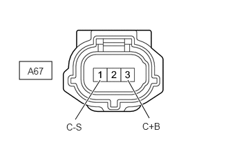
| *a | Front view of wire harness connector
(to Clutch Stroke Sensor) |
Disconnect the clutch stroke sensor connector.
Measure the voltage according to the value(s) in the table below.
- Standard Voltage:
Tester Connection Switch Condition Specified Condition A67-3 (C+B) - A67-1 (C-S) Ignition switch ON 4.5 to 5.5 V
- Result:
Proceed to OK NG
OK
NG
Inspect the clutch stroke sensor.
Click hereDrivetrain>CLUTCH>CLUTCH MASTER CYLINDER(w/ Turn Over)>ON-VEHICLE INSPECTION
- Result:
Proceed to OK NG
OK
NG
Refer to the "Clutch slips" item in the problem symptoms table for the clutch system and check each part.
Click hereDrivetrain>CLUTCH>CLUTCH SYSTEM>PROBLEM SYMPTOMS TABLE
- OK:
Inspections of all suspected areas are normal.
- Result:
Proceed to OK NG
OK
NG
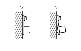
| *a | CORRECT |
| *b | INCORRECT |
Check the transmission revolution sensor installation.
- OK:
The installation bolt is tightened properly and there is no clearance between the sensor and transmission case.
- Result:
Proceed to OK NG
OK
NG
Disconnect the transmission revolution sensor connector.
Disconnect the ECM connector.
Measure the resistance according to the value(s) in the table below.
- Standard Resistance:
Tester Connection Condition Specified Condition C4-2 (NMB) - C40-12 (NIMB) Always Below 1 Ω C4-1 (NMO) - C40-13 (NIMO) Always Below 1 Ω C4-2 (NMB) - Body ground Always 10 kΩ or higher C4-1 (NMO) - Body ground Always 10 kΩ or higher
- Result:
Proceed to OK NG
OK
NG
Inspect transmission revolution sensor.
Click hereDrivetrain>RC60 / RC61 MANUAL TRANSMISSION / TRANSAXLE>SPEED SENSOR>INSPECTION
- Result:
Proceed to OK NG
OK
NG
Inspect the teeth of the countershaft 2nd speed gear.
- OK:
No tooth damage on countershaft 2nd speed gear.
- Result:
Proceed to OK NG
OK
NG