Home › Audio / Visual / Telematics › PARK ASSIST / MONITORING › TOYOTA PARKING ASSIST-SENSOR SYSTEM
RM1880E _56 Audio / Visual / Telematics _013235 PARK ASSIST / MONITORING _0068601 TOYOTA PARKING ASSIST-SENSOR SYSTEM J

PARK ASSIST / MONITORING  TOYOTA PARKING ASSIST-SENSOR SYSTEM  Back Sonar Sensor Circuit  


DESCRIPTION

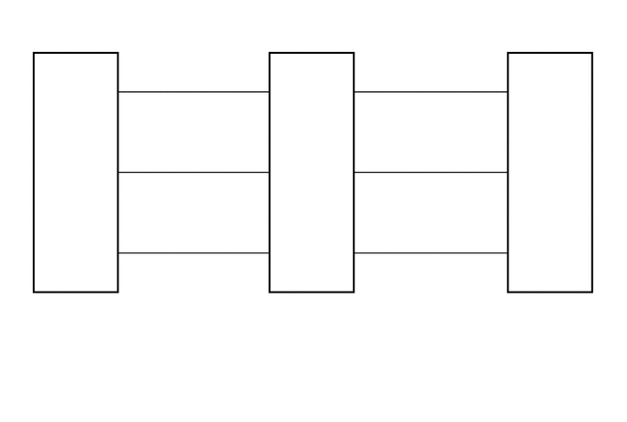
This circuit includes the sensor power supply, sensor ground, and sensor signal wires between the rear clearance warning ECU assembly and No. 1 ultrasonic sensors. The No. 1 ultrasonic sensors are digital sensors.

WIRING DIAGRAM
E227688
5.552,3.354 7.156,3.677 1.604,0.323 10 false T1 5.552,3.531 7.125,4.021 1.573,0.49 10 false Rear Clearance Warning ECU Assembly 2.823,3.354 4.406,3.615 1.583,0.26 10 false T3 2.823,3.531 4.302,4.073 1.479,0.542 10 false No. 1 Ultrasonic Sensor (Rear Sensor RH) 0.104,3.354 1.74,3.615 1.635,0.26 10 false T2 0.104,3.531 1.615,3.99 1.51,0.458 10 false No. 1 Ultrasonic Sensor (Rear Sensor LH) 1.396,0.854 1.698,1.063 0.302,0.208 10 false 1 2.917,2.677 3.135,2.927 0.219,0.25 10 false 6 4.094,0.865 4.396,1.125 0.302,0.26 10 false 1 2.917,1.771 3.271,2.073 0.354,0.302 10 false 4 4.094,2.677 4.313,2.823 0.219,0.146 10 false 5 1.396,1.771 1.615,1.917 0.219,0.146 10 false 3 1.146,0.979 1.427,1.156 0.281,0.177 10 false BI 1.146,2.823 1.438,3.073 0.292,0.25 10 false EI 1.146,1.906 1.396,2.135 0.25,0.229 10 false SI 2.917,0.865 3.177,1.094 0.26,0.229 10 false 2 1.396,2.677 1.615,2.823 0.219,0.146 10 false 5 4.094,1.771 4.313,1.917 0.219,0.146 10 false 3 3.125,0.979 3.406,1.229 0.281,0.25 10 false BO 3.844,2.823 4.135,3.094 0.292,0.271 10 false EI 3.125,1.865 3.438,2.135 0.313,0.271 10 false SO 3.844,0.99 4.135,1.25 0.292,0.26 10 false BI 5.854,1.865 6.365,2.219 0.51,0.354 10 false SOR 3.125,2.813 3.438,3.135 0.313,0.323 10 false EO 5.854,0.958 6.365,1.25 0.51,0.292 10 false BOR 5.854,2.802 6.365,3.083 0.51,0.281 10 false E2 3.844,1.865 4.135,2.198 0.292,0.333 10 false SI 5.583,0.865 5.906,1.156 0.323,0.292 10 false 24 5.667,1.771 5.969,2.125 0.302,0.354 10 false 6 5.583,2.677 5.875,2.969 0.292,0.292 10 false 22

PROCEDURE

1.CHECK REAR CLEARANCE WARNING ECU ASSEMBLY
E187467
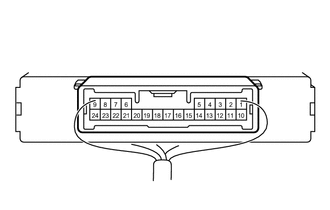
1.458,0.354 1.958,0.604 0.5,0.25 1.198,1.229 1.781,1.896 1.781,1.896 1.927,1.896 true 0.979,1.229 0.813,1.885 0.813,1.885 0.708,1.885 true 0.219,0.188 0.5,0.458 0.281,0.271 10 false *a 1.635,0.406 1.917,0.74 0.281,0.333 10 false T1 1.99,1.781 2.313,2.073 0.323,0.292 10 false E2 0.354,1.771 0.885,2.042 0.531,0.271 10 false BOR
*a Component with harness connected
(Rear Clearance Warning ECU Assembly)


a.

Measure the resistance according to the value(s) in the table below.

Standard Resistance:
Tester Connection Condition Specified Condition
T1-22 (E2) - Body ground Always Below 1 Ω


b.

Measure the voltage according to the value(s) in the table below.

Standard Voltage:
Tester Connection Switch Condition Specified Condition
T1-24 (BOR) - T1-22 (E2) Ignition switch ON, back sonar or clearance sonar switch on 7.2 to 8.8 V


Result:
Proceed to
OK
NG


OK

2.CHECK HARNESS AND CONNECTOR (REAR CLEARANCE WARNING ECU ASSEMBLY- REAR SENSOR RH)

NG

REPLACE REAR CLEARANCE WARNING ECU ASSEMBLY

2.CHECK HARNESS AND CONNECTOR (REAR CLEARANCE WARNING ECU ASSEMBLY- REAR SENSOR RH)
a.

Disconnect the T1 rear clearance warning ECU assembly connector.


b.

Disconnect the T3 No. 1 ultrasonic sensor (rear sensor RH) connector.


c.

Measure the resistance according to the value(s) in the table below.

Standard Resistance:
Tester Connection Condition Specified Condition
T1-24 (BOR) - T3-1 (BI) Always Below 1 Ω
T1-6 (SOR) - T3-3 (SI) Always Below 1 Ω
T1-22 (E2) - T3-5 (EI) Always Below 1 Ω
T1-24 (BOR) - Body ground Always 10 kΩ or higher
T1-6 (SOR) - Body ground Always 10 kΩ or higher
T1-22 (E2) - Body ground Always 10 kΩ or higher


Result:
Proceed to
OK
NG


OK

3.CHECK HARNESS AND CONNECTOR (REAR SENSOR RH - REAR SENSOR LH)

NG

REPAIR OR REPLACE HARNESS OR CONNECTOR

3.CHECK HARNESS AND CONNECTOR (REAR SENSOR RH - REAR SENSOR LH)
a.

Disconnect the T3 No. 1 ultrasonic sensor (rear sensor RH) connector.


b.

Disconnect the T2 No. 1 ultrasonic sensor (rear sensor LH) connector.


c.

Measure the resistance according to the value(s) in the table below.

Standard Resistance:
Tester Connection Condition Specified Condition
T3-2 (BO) - T2-1 (BI) Always Below 1 Ω
T3-4 (SO) - T2-3 (SI) Always Below 1 Ω
T3-6 (EO) - T2-5 (EI) Always Below 1 Ω
T3-2 (BO) - Body ground Always 10 kΩ or higher
T3-4 (SO) - Body ground Always 10 kΩ or higher
T3-6 (EO) - Body ground Always 10 kΩ or higher


Result:
Proceed to
OK
NG


OK

4.INSPECT NO. 1 ULTRASONIC SENSOR (REAR SENSOR RH)

NG

REPAIR OR REPLACE HARNESS OR CONNECTOR

4.INSPECT NO. 1 ULTRASONIC SENSOR (REAR SENSOR RH)
a.

Remove the No. 1 ultrasonic sensor (rear sensor RH).

Click hereAudio / Visual / Telematics>PARK ASSIST / MONITORING>ULTRASONIC SENSOR>REMOVAL

b.
E186403
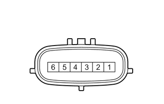
2.302,1.479 2.625,1.833 2.625,1.833 2.792,1.833 true 2.083,1.333 2.438,0.896 2.438,0.896 2.802,0.896 true 1.125,1.479 0.813,1.833 0.813,1.833 0.635,1.833 true 1.365,1.323 1.01,0.885 1.01,0.885 0.635,0.885 true 1.594,1.333 2.042,0.667 2.042,0.667 2.406,0.667 true 1.823,1.479 2.135,2.042 2.135,2.042 2.302,2.042 true 2.865,1.771 3.229,2.031 0.365,0.26 10 false BI 2.865,0.823 3.229,1.156 0.365,0.333 10 false BO 2.375,1.938 2.688,2.177 0.313,0.24 10 false SI 2.458,0.594 2.854,0.906 0.396,0.313 10 false SO 0.417,0.823 0.75,1.135 0.333,0.313 10 false EI 0.385,1.75 0.74,2.01 0.354,0.26 10 false EO

Measure the resistance according to the value(s) in the table below.

Standard Resistance:
Tester Connection Condition Specified Condition
1 (BI) - 5 (EI) Always 10 kΩ or higher
1 (BI) - 2 (BO) Always 10 kΩ or higher
3 (SI) - 4 (SO) Always Below 1 Ω
5 (EI) - 6 (EO) Always Below 1 Ω


Result:
Proceed to
OK
NG


OK

5.CHECK TOYOTA PARKING ASSIST-SENSOR SYSTEM

NG

REPLACE NO. 1 ULTRASONIC SENSOR (REAR SENSOR RH)

5.CHECK TOYOTA PARKING ASSIST-SENSOR SYSTEM
a.

Check the operation of the TOYOTA parking assist-sensor system.

Click hereAudio / Visual / Telematics>PARK ASSIST / MONITORING>TOYOTA PARKING ASSIST-SENSOR SYSTEM>OPERATION CHECK

Result:
Result Proceed to
TOYOTA parking assist-sensor system malfunction A
TOYOTA parking assist-sensor system normal operation B


A

6.REPLACE NO. 1 ULTRASONIC SENSOR (REAR SENSOR LH)

B

END

6.REPLACE NO. 1 ULTRASONIC SENSOR (REAR SENSOR LH)
a.

Replace the No. 1 ultrasonic sensor (rear sensor LH).

Click hereAudio / Visual / Telematics>PARK ASSIST / MONITORING>ULTRASONIC SENSOR>REMOVAL


Result:
Proceed to
NEXT


NEXT

7.CHECK TOYOTA PARKING ASSIST-SENSOR SYSTEM
a.

Check the operation of the TOYOTA parking assist-sensor system.

Click hereAudio / Visual / Telematics>PARK ASSIST / MONITORING>TOYOTA PARKING ASSIST-SENSOR SYSTEM>OPERATION CHECK

Result:
Result Proceed to
TOYOTA parking assist-sensor system malfunction A
TOYOTA parking assist-sensor system normal operation B


A

8.REPLACE NO. 1 ULTRASONIC SENSOR (REAR SENSOR RH)

B

END (NO. 1 ULTRASONIC SENSOR [REAR SENSOR LH] IS DEFECTIVE)

8.REPLACE NO. 1 ULTRASONIC SENSOR (REAR SENSOR RH)
a.

Replace the No. 1 ultrasonic sensor (rear sensor RH).

Click hereAudio / Visual / Telematics>PARK ASSIST / MONITORING>ULTRASONIC SENSOR>REMOVAL


Result:
Proceed to
NEXT


NEXT

9.CHECK TOYOTA PARKING ASSIST-SENSOR SYSTEM
a.

Check the operation of the TOYOTA parking assist-sensor system.

Click hereAudio / Visual / Telematics>PARK ASSIST / MONITORING>TOYOTA PARKING ASSIST-SENSOR SYSTEM>OPERATION CHECK

Result:
Result Proceed to
TOYOTA parking assist-sensor system malfunction A
TOYOTA parking assist-sensor system normal operation B


A

PROCEED TO NEXT SUSPECTED AREA SHOWN IN PROBLEM SYMPTOMS TABLE

B

END (NO. 1 ULTRASONIC SENSOR [REAR SENSOR RH] IS DEFECTIVE)