Display Signal Circuit between Video Terminal and Television Display
Circuit diagnosis · Vehicles built from Aug 2014
Versions by build date: Aug 2013 – Jul 2014 from Aug 2014
DESCRIPTION
This is the display signal from the video (video adapter) terminal to the television display assembly.WIRING DIAGRAM
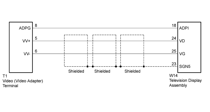

INSPECTION PROCEDURE
| 1. CHECK HARNESS AND CONNECTOR (TELEVISION DISPLAY ASSEMBLY - VIDEO [VIDEO ADAPTER] TERMINAL) |

Disconnect the W14 television display assembly connector.
Disconnect the T1 video (video adapter) terminal connector.
Measure the resistance according to the value(s) in the table below.
- Standard Resistance:
Tester Connection
Condition
Specified Condition
W14-18 (ADPI) - T1-8 (ADPG)
Always
Below 1 Ω
W14-24 (VD+) - T1-5 (VV+)
Always
Below 1 Ω
W14-25 (VG) - T1-6 (VV-)
Always
Below 1 Ω
W14-23 (SGN5) - Body ground
Always
10 kΩ or higher
W14-18 (ADPI) - Body ground
Always
10 kΩ or higher
W14-24 (VD+) - Body ground
Always
10 kΩ or higher
W14-25 (VG) - Body ground
Always
10 kΩ or higher
|
|
||||

| OK | |
 |
| 2. CHECK VIDEO (VIDEO ADAPTER) TERMINAL |
Remove the video (video adapter) terminal connector still connected (Click here).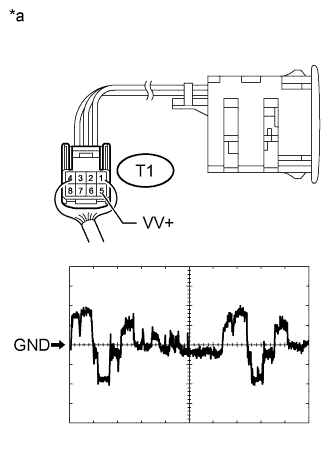
Using an oscilloscope, check the waveform.
Measurement Condition Item
Content
Terminal No. (Symbol)
T1-5 (VV+) - Body ground
Tool Setting
0.2 V/DIV., 0.2 μs./DIV.
Condition
External device playing, VTR displayed
- OK:
- Waveform is as shown in the illustration.
Text in Illustration *a
Component with harness connected
(Video [Video Adapter] Terminal)
|
|
||||
| OK | ||
 |
||
| ||