Sound Signal Circuit between Headphone Terminal and Television Display
Circuit diagnosis · Vehicles built from Aug 2014
Versions by build date: Aug 2013 – Jul 2014 from Aug 2014
DESCRIPTION
This circuit sends a sound signal from the television display to the headphone terminal.WIRING DIAGRAM
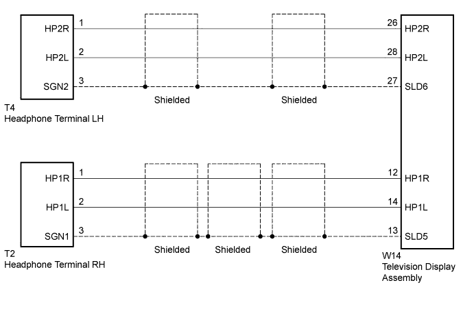

INSPECTION PROCEDURE
| 1. CHECK HEADPHONES |

Check the malfunctioning headphones.
Result Result
Proceed to
Malfunction in headphone terminal LH side
A
Malfunction in headphone terminal RH side
B
|
|
||||

| A | |
 |
| 2. CHECK HARNESS AND CONNECTOR (TELEVISION DISPLAY ASSEMBLY - HEADPHONE TERMINAL LH) |
Disconnect the W14 television display assembly connector.
Disconnect the T4 headphone terminal LH connector.
Measure the resistance according to the value(s) in the table below.
- Standard Resistance:
Tester Connection
Condition
Specified Condition
W14-26 (HP2R) - T4-1 (HP2R)
Always
Below 1 Ω
W14-27 (SLD6) - T4-3 (SGN2)
Always
Below 1 Ω
W14-28 (HP2L) - T4-2 (HP2L)
Always
Below 1 Ω
W14-26 (HP2R) - Body ground
Always
10 kΩ or higher
W14-27 (SLD6) - Body ground
Always
10 kΩ or higher
W14-28 (HP2L) - Body ground
Always
10 kΩ or higher
|
|
||||

| OK | |
|
| 3. CHECK TELEVISION DISPLAY ASSEMBLY |
Remove the television display assembly connector still connected (Click here).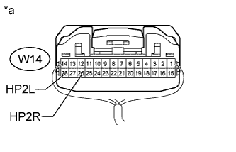
Using an oscilloscope, check the waveform between each terminal and the body ground according to the conditions as shown in the table below.
- Standard:
Tester Connection
Condition
Specified Condition
W14-26 (HP2R) - Body ground
Audio sound being produced
A waveform synchronized with sound is output
W14-28 (HP2L) - Body ground
Text in Illustration *a
Component with harness connected
(Television Display Assembly)
|
|
||||
| OK | ||
 |
||
| ||
| 4. CHECK HARNESS AND CONNECTOR (TELEVISION DISPLAY ASSEMBLY - HEADPHONE TERMINAL RH) |
Disconnect the W14 television display assembly connector.
Disconnect the T2 headphone terminal RH connector.
Measure the resistance according to the value(s) in the table below.
- Standard Resistance:
Tester Connection
Condition
Specified Condition
W14-12 (HP1R) - T2-1 (HP1R)
Always
Below 1 Ω
W14-13 (SLD5) - T2-3 (SGN1)
Always
Below 1 Ω
W14-14 (HP1L) - T2-2 (HP1L)
Always
Below 1 Ω
W14-12 (HP1R) - Body ground
Always
10 kΩ or higher
W14-13 (SLD5) - Body ground
Always
10 kΩ or higher
W14-14 (HP1L) - Body ground
Always
10 kΩ or higher
|
|
||||
| OK | |
|
| 5. CHECK TELEVISION DISPLAY ASSEMBLY |
Remove the television display assembly connector still connected (Click here).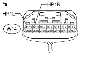
Using an oscilloscope, check the waveform between each terminal and the body ground according to the conditions as shown in the table below.
- Standard:
Tester Connection
Condition
Specified Condition
W14-12 (HP1R) - Body ground
Audio sound being produced
A waveform synchronized with sound is output
W14-14 (HP1L) - Body ground
Text in Illustration *a
Component with harness connected
(Television Display Assembly)
|
|
||||
| OK | ||
|
||
| ||