C1791/91 Adaptive Variable Suspension (AVS) Switch Circuit (Test Mode DTC)
Diagnostic trouble codes · Vehicles built Aug 2013 – Jul 2014
Versions by build date: Aug 2013 – Jul 2014 from Aug 2014
DESCRIPTION
The absorber control switch is used to select the damping force mode of the shock absorber.| DTC Code |
DTC Detection Condition |
Trouble Area |
| C1791/91 |
The absorber control switch signal does not change. |
|
- HINT:
- This DTC is stored only during test mode.
WIRING DIAGRAM
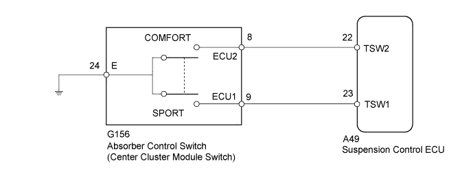

INSPECTION PROCEDURE
- NOTICE:
- When replacing the suspension control ECU, perform registration (Click here).
| 1. READ VALUE USING INTELLIGENT TESTER (DAMPING CONTROL SWITCH) |

Turn the ignition switch off.
Connect the intelligent tester to the DLC3.
Turn the ignition switch to ON.
Turn the intelligent tester on.
Enter the following menus: Chassis / Air suspension / Data List.
Air Suspension Tester Display
Measurement Item/Range
Normal Condition
Diagnostic Note
Damping Control Switch
Absorber control switch /
NORMAL, COMFORT or SPORT
Indicates current absorber control switch position
-
Check that the value displayed on the intelligent tester changes by operating the absorber control switch between COMF, NORMAL and SPORT.
- OK:
- Absorber control switch value changes.
|
|
||||

| OK | ||
 |
||
| ||
| 2. INSPECT CENTER CLUSTER MODULE SWITCH |
Turn the ignition switch off.
Remove the absorber control switch (center cluster module switch) (Click here).
Measure the resistance according to the value(s) in the table below.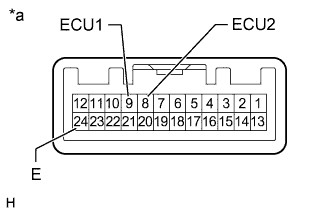
- Standard Resistance:
Tester Connection
Switch Condition
Specified Condition
24 (E) - 9 (ECU1)
SPORT position
Below 1 Ω
Normal position
10 kΩ or higher
24 (E) - 8 (ECU2)
COMF position
Below 1 Ω
Normal position
10 kΩ or higher
Text in Illustration *a
Component without harness connected
(Absorber Control Switch (Center Cluster Module Switch))
|
|
||||

| OK | |
 |
| 3. CHECK HARNESS AND CONNECTOR (CENTER CLUSTER MODULE SWITCH - SUSPENSION CONTROL ECU) |
Disconnect the G156 absorber control switch (center cluster module switch) connector.
Disconnect the A49 suspension control ECU connector.
Measure the resistance according to the value(s) in the table below.
- Standard Resistance:
Tester Connection
Condition
Specified Condition
G156-9 (ECU1) - A49-23 (TSW1)
Always
Below 1 Ω
G156-8 (ECU2) - A49-22 (TSW2)
Always
Below 1 Ω
G156-24 (E) - Body ground
Always
Below 1 Ω
G156-9 (ECU1) or A49-23 (TSW1) - Body ground
Always
10 kΩ or higher
G156-8 (ECU2) or A49-22 (TSW2) - Body ground
Always
10 kΩ or higher
|
|
||||
| OK | ||
|
||
| ||