Wiper Signal Circuit
Circuit diagnosis · Vehicles built Aug 2013 – Jul 2014
Versions by build date: Aug 2013 – Jul 2014 from Aug 2014
DESCRIPTION
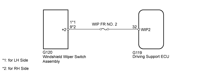
When the driving support ECU detects that the wipers are operating at high speed, the dynamic radar cruise control system is canceled.WIRING DIAGRAM

INSPECTION PROCEDURE
- NOTICE:
- Inspect the fuses for circuits related to this system before performing the following inspection procedure.
| 1. CHECK WINDSHIELD WIPER SWITCH ASSEMBLY |

Measure the voltage according to the value(s) in the table below.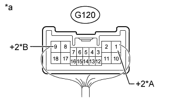
- Standard Voltage:
Tester Connection
Switch Condition
Specified Condition
1 (+2) - Body ground*1
9 (+2) - Body ground*2
Ignition switch ON, windshield wiper switch Hi
11 to 14 V
Ignition switch ON, windshield wiper switch Lo
Approximately 9 V
Ignition switch ON, windshield wiper switch off
Below 1 V
- *1: for LH Side
- *2: for RH Side
Text in illustration *A
for RH Side
*B
for LH Side
*a
Component with harness connected
(Windshield Wiper Switch Assembly)
|
|
||||

| OK | |
 |
| 2. CHECK HARNESS AND CONNECTOR (WINDSHIELD WASHER SWITCH - DRIVING SUPPORT ECU) |
Disconnect the G119 ECU connector.
Disconnect the G120 switch connector.
Measure the resistance according to the value(s) in the table below.
- Standard Resistance:
Tester Connection
Condition
Specified Condition
G119-32 (WIP2) - G120-1 (+2)*1
Always
Below 1 Ω
G119-32 (WIP2) - G120-9 (+2)*2
G119-32 (WIP2) - Body ground
Always
10 kΩ or higher
- *1: for LH Side
- *2: for RH Side
|
|
||||
| OK | ||
 |
||
| ||