2013-2015 Land Cruiser Prado · Service Manual Engine / Hybrid System

REMOVAL

Removal / installation · Vehicles built from Aug 2014

Versions by build date: Aug 2013 – Jul 2014 from Aug 2014

NOTICE:
  1. When replacing the injectors (including shuffling the injectors between the cylinders), common rail or cylinder head, it is necessary to replace the injection pipes with new ones.
  2. When replacing the fuel supply pump, common rail, cylinder block, cylinder head, cylinder head gasket or timing gear case, it is necessary to replace the fuel inlet pipe with a new one.
  3. After removing the fuel inlet pipe, clean them with a brush and compressed air.


1. DISCONNECT CABLE FROM NEGATIVE BATTERY TERMINAL

NOTICE:
  1. After turning the ignition switch off, waiting time may be required before disconnecting the cable from the battery terminal. Therefore, make sure to read the disconnecting the cable from the battery terminal notice before proceeding with work (Click here).
  2. When disconnecting the cable, some systems need to be initialized after the cable is reconnected (Click here).

2. REMOVE TIMING BELT
  1. Remove the timing belt (Click here).


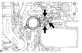
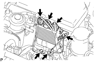
3. REMOVE INJECTOR DRIVER

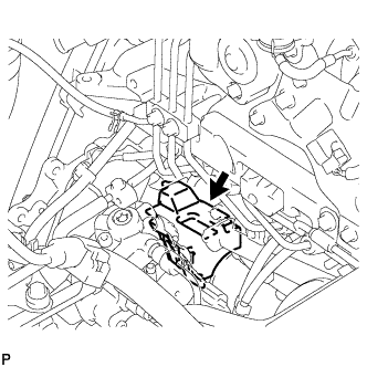
  1. A220753
    Disconnect the 3 connectors.

  1. Remove the 3 bolts and injector driver assembly.


4. DISCONNECT VANE PUMP OIL RESERVOIR ASSEMBLY

  1. A223237
    Remove the 3 bolts and disconnect the vane pump oil reservoir.


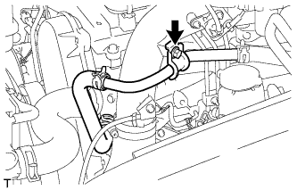
5. DISCONNECT HEATER WATER PIPE SUB-ASSEMBLY

  1. A224418
    Remove the bolt and disconnect the inlet heater water hose.


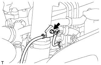
6. DISCONNECT NO. 4 VACUUM TRANSMITTING PIPE SUB-ASSEMBLY

  1. A222558
    Remove the bolt and disconnect the No. 4 vacuum transmitting pipe.


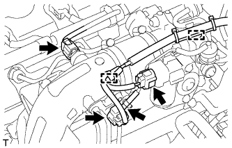
7. REMOVE NO. 1 INTAKE PIPE

  1. A222559
    Disconnect the 3 connectors from the intake air temperature sensor, throttle control motor and manifold absolute pressure sensor.

  1. Detach the 2 clamps.

  1. Disconnect the vacuum hose from the manifold absolute pressure sensor.

  1. A222560
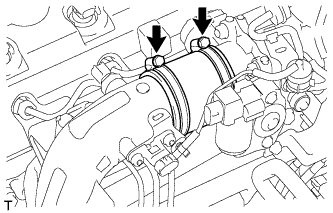
    Loosen the 2 hose clamps of the No. 1 air hose.

  1. A222561
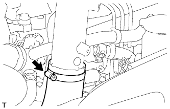
    Loosen the hose clamp of the intercooler air hose.

  1. A222562
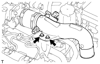
    Remove the 2 bolts and No. 1 intake pipe.


8. REMOVE FUEL INLET PIPE SUB-ASSEMBLY

  1. A152732
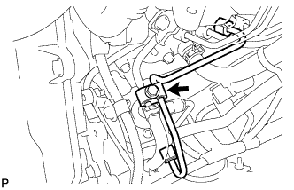
    Remove the bolt and clamp.

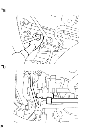
  1. A152733E02
    Using a 17 mm union nut wrench, loosen the union nuts and remove the fuel inlet pipe.
    Text in Illustration 
    *a
    Common Rail Side
    *b
    Fuel Supply Pump Side


9. REMOVE FUEL SUPPLY PUMP INSULATOR

A223244

10. REMOVE NO. 1 FUEL SUPPLY PUMP PROTECTOR

  1. A223246
    Remove the 2 bolts and No. 1 fuel supply pump protector.


11. REMOVE FUEL SUPPLY PUMP ASSEMBLY

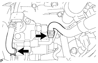
  1. A228335
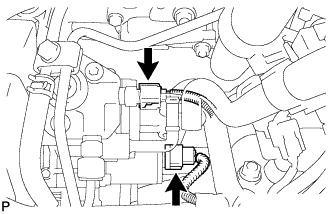
    Disconnect the 2 fuel hoses.

  1. A228336
    Disconnect the fuel temperature sensor connector and suction control valve connector.

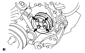
  1. A070710E01
    Remove the 4 bolts indicated by the arrows in the illustration.

  1. Remove the No. 2 camshaft timing pulley flange and pump drive shaft pulley.

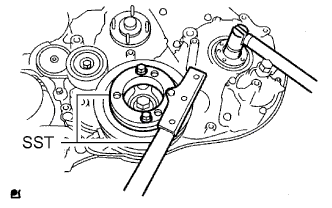
  1. A070711E05
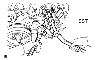
    Remove the set nut and O-ring while holding the crankshaft pulley using SST.
    SST
    09213-58014  
    09330-00021  

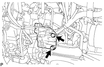
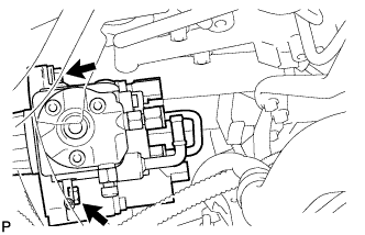
  1. A228337
    Loosen the 2 nuts.

  1. A070714E03
    Using SST, disconnect the fuel supply pump from the supply pump gear.
    SST
    09950-50013   (09951-05010, 09952-05010, 09953-05020, 09954-05021)

    NOTICE:
    Apply lubricant to the threads and tip of SST (center bolt) before using it.

  1. Remove the 2 nuts and fuel supply pump.

    NOTICE:
    1. Do not hold or carry the fuel supply pump by holding the pipe.
    2. The fuel supply pump must be kept horizontal.

  1. Remove the O-ring.

← REMOVAL (Aug 2013 – Jul 2014)INSPECTION (from Aug 2013) →