RM27T0E
_51
Engine / Hybrid System
_053658
5L-E ENGINE CONTROL
_0260445
ECD SYSTEM
J
5L-E ENGINE CONTROL ECD SYSTEM Air Conditioning Signal Circuit
DESCRIPTION
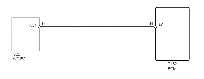
When the A/C compressor is on, the A/C amplifier sends the A/C signal to the ECM and the ECM increases the fuel injection volume to improve driveability during engine idling.
WIRING DIAGRAM
5.896,2.354 6.333,2.552
0.438,0.198
10
false
ECM
0.448,2 1.365,2.208
0.917,0.208
10
false
A/C ECU
0.448,1.833 1.438,2.063
0.99,0.229
10
false
G25
5.885,2.177 6.313,2.344
0.427,0.167
10
false
G182
5.563,0.802 6,1
0.438,0.198
10
false
AC1
5.229,0.75 5.438,0.938
0.208,0.188
10
false
34
1.021,0.813 1.458,1.01
0.438,0.198
10
false
AC1
1.448,0.75 2.083,0.938
0.635,0.188
10
false
17
PROCEDURE
1.READ VALUE USING GTS (AIR CONDITIONING SIGNAL)
a.
Connect the GTS to the DLC3.
b.
Start the engine.
c.
Turn the A/C switch on.
d.
Enter the following menus: Powertrain / Engine and ECT / Data List / A/C SIG.
- Result:
Switch Condition A/C SIG A/C switch off OFF A/C switch on ON
OK
PROCEED TO NEXT SUSPECTED AREA SHOWN IN PROBLEM SYMPTOMS TABLE
NG
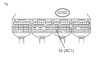
2.CHECK ECM (AC1 VOLTAGE)
2.CHECK ECM (AC1 VOLTAGE)
a.
1.917,1.031 2.198,1.635
false
1.958,0.344 2.396,0.51
0.438,0.167
10
false
G182
0.135,0.052 0.365,0.219
0.229,0.167
10
false
*a
1.979,1.646 2.583,1.833
0.604,0.188
10
false
34 (AC1)
Start the engine.
b.
Measure the voltage according to the value(s) in the table below.
- Standard Voltage:
Tester Connection Switch Condition Specified Condition G182-34 (AC1) - Body ground A/C switch on Below 1.5 V G182-34 (AC1) - Body ground A/C switch off 7.5 to 14 V
| *a | Component with harness connected
(ECM) |
OK
NG
3.CHECK HARNESS AND CONNECTOR (ECM - AIR CONDITIONING AMPLIFIER)
3.CHECK HARNESS AND CONNECTOR (ECM - AIR CONDITIONING AMPLIFIER)
a.
Disconnect the A/C amplifier connector.
b.
Disconnect the ECM connector.
c.
Measure the resistance according to the value(s) in the table below.
- Standard Resistance:
Tester Connection Condition Specified Condition G25-17 (AC1) - G182-34 (AC1) Always Below 1 Ω G25-17 (AC1) or G182-34 (AC1) - Body ground Always 10 kΩ or higher
d.
Reconnect the A/C amplifier connector.
e.
Reconnect the ECM connector.
OK
REPLACE AIR CONDITIONING AMPLIFIER
NG
REPAIR OR REPLACE HARNESS OR CONNECTOR