1KD-FTV FUEL FUEL SUPPLY PUMP INSTALLATION
CAUTION / NOTICE / HINT
- NOTICE:
- ·
When replacing the injectors (including shuffling the injectors between the cylinders), common rail or cylinder head, it is necessary to replace the injection pipes with new ones.
·When replacing the fuel supply pump, common rail, cylinder block, cylinder head, cylinder head gasket or timing gear case, it is necessary to replace the fuel inlet pipe with a new one.
PROCEDURE

 22100
1.INSTALL FUEL SUPPLY PUMP ASSEMBLY
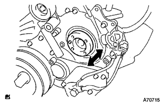
Check that the supply pump gear in the timing gear case moves back and forth smoothly.
Install a new O-ring to the fuel supply pump.
Apply a light coat of engine oil to the O-ring.
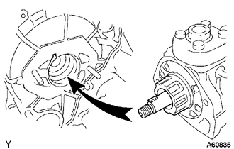
Align the groove of the supply pump gear with the set key on the drive shaft.
Install the fuel supply pump with the 2 nuts.
- Torque:
- 21 N*m (214 kgf*cm, 15 ft.*lbf)
Install a new O-ring.
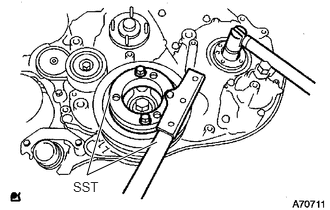
Using SST, hold the crankshaft pulley and install the set nut.
- SST
- 09213-58014
09330-00021
- Torque:
- 64 N*m (650 kgf*cm, 47 ft.*lbf)
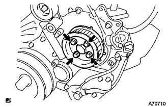
Install the pump drive shaft pulley and No. 2 camshaft timing pulley flange with the 4 bolts.
- Torque:
- 31 N*m (316 kgf*cm, 23 ft.*lbf)
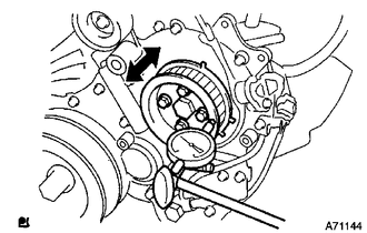
Move the pump drive shaft pulley back and forth to check the thrust clearance of the injection pump drive shaft.
- Standard thrust clearance:
0.15 to 0.55 mm (0.00590 to 0.0217 in.)
If the clearance is not within the specified range, disassemble and reassemble the supply pump and pump drive shaft pulley. Then repeat the step above.
Connect the fuel temperature sensor connector and suction control valve connector.
Connect the 2 fuel hoses.
22813
2.INSTALL NO. 1 FUEL SUPPLY PUMP PROTECTOR
Install the No. 1 fuel supply pump protector with the 2 bolts.
- Torque:
- 29 N*m (296 kgf*cm, 21 ft.*lbf)
22815A
3.INSTALL FUEL SUPPLY PUMP INSULATOR
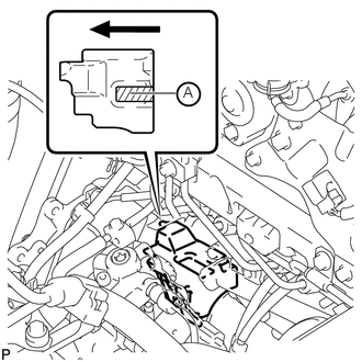
Install the fuel supply pump insulator.

|
Front Side of Vehicle |
- NOTICE:
- ·
When installing the fuel pump supply insulator, be sure to hold down the part labeled A in the illustration.
·Make sure that the shape of the fuel supply pump insulator fits correctly with the timing gear case, cylinder block and oil cooler cover.
23804C
4.INSTALL FUEL INLET PIPE SUB-ASSEMBLY
Temporarily install the fuel inlet pipe with the union nuts.
- NOTICE:
- ·
When replacing the fuel supply pump, it is necessary to replace the fuel inlet pipe with a new one.
·Keep the fuel inlet pipe free of foreign matter.
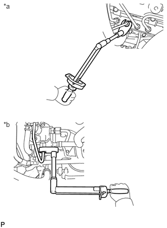
Using a 17 mm union nut wrench, tighten the fuel inlet pipe union nut on the common rail side.
- Torque:
- 35 N*m (357 kgf*cm, 26 ft.*lbf)
| *a | Common Rail Side |
| *b | Fuel Supply Pump Side |
- NOTICE:
-
Use the formula to calculate special torque values for situations where a union nut wrench is combined with a torque wrench (See page General>INTRODUCTION>REPAIR INSTRUCTION>PRECAUTION).
Using a 17 mm union nut wrench, tighten the fuel inlet pipe union nut on the fuel supply pump side.
- Torque:
- 35 N*m (357 kgf*cm, 26 ft.*lbf)
- NOTICE:
-
Use the formula to calculate special torque values for situations where a union nut wrench is combined with a torque wrench (See page General>INTRODUCTION>REPAIR INSTRUCTION>PRECAUTION).
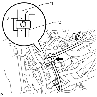
Install the clamp with the bolt.
- Torque:
- 5.0 N*m (51 kgf*cm, 44 in.*lbf)
| *1 | No. 2 Nozzle Leakage Pipe |
| *2 | Fuel Inlet Pipe |
| *3 | Spool |
- NOTICE:
- ·
Install the clamp between the spools.
·Do not overlap the clamp and spool.
17113E
5.INSTALL NO. 1 INTAKE PIPE
25709E
6.CONNECT NO. 4 VACUUM TRANSMITTING PIPE SUB-ASSEMBLY
87208A
7.CONNECT HEATER WATER PIPE SUB-ASSEMBLY
44360
8.CONNECT VANE PUMP OIL RESERVOIR ASSEMBLY
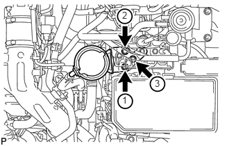
Temporarily install the vane pump oil reservoir with the 3 bolts.
Tighten the 3 bolts of the vane pump oil reservoir in the order shown in the illustration.
- Torque:
- 8.0 N*m (82 kgf*cm, 71 in.*lbf)
89871A
9.INSTALL INJECTOR DRIVER
13568
10.INSTALL TIMING BELT
Install the timing belt (See page Engine / Hybrid System>1KD-FTV (ENGINE MECHANICAL)>TIMING BELT>INSTALLATION).
11.CONNECT CABLE TO NEGATIVE BATTERY TERMINAL
- NOTICE:
-
When disconnecting the cable, some systems need to be initialized after the cable is reconnected (See page General>INTRODUCTION>REPAIR INSTRUCTION>INITIALIZATION).
12.ADD ENGINE COOLANT
13.BLEED AIR FROM FUEL SYSTEM
14.INSPECT FOR COOLANT LEAK
15.INSPECT FOR FUEL LEAK