5L-E INTAKE / EXHAUST EXHAUST MANIFOLD INSTALLATION
PROCEDURE

 17141
1.INSTALL EXHAUST MANIFOLD
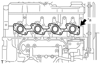
Install a new gasket to the cylinder head.
| *a | Front Mark |
- HINT:
-
Be sure to install a new gasket in the correct direction as shown in the illustration.
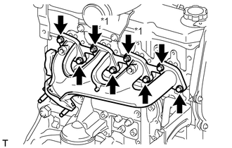
Install the exhaust manifold with the 6 bolts and 2 new nuts. Uniformly tighten the bolts and nuts in several steps.
- Torque:
- 52 N*m (530 kgf*cm, 38 ft.*lbf)
| *1 | Nut |
17167
2.INSTALL NO. 1 EXHAUST MANIFOLD HEAT INSULATOR
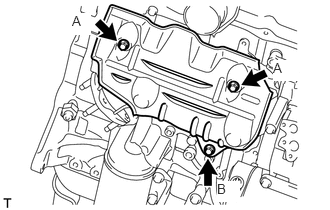
Install the insulator with the 3 bolts.
- Torque:
- for bolt A : 18 N*m (185 kgf*cm, 13 ft.*lbf)
- for bolt B : 19 N*m (195 kgf*cm, 14 ft.*lbf)
11452
3.INSTALL ENGINE OIL LEVEL DIPSTICK GUIDE
Apply clean engine oil to a new O-ring.
Install the O-ring to the guide.
Install the guide with the 2 bolts.
- Torque:
- 18 N*m (185 kgf*cm, 13 ft.*lbf)
15301
4.INSTALL ENGINE OIL LEVEL DIPSTICK
Install the oil level dipstick to the guide.
17410
5.INSTALL FRONT EXHAUST PIPE ASSEMBLY
17130
6.INSTALL INTAKE PIPE
7.INSTALL RESONATOR WITH AIR CLEANER CAP SUB-ASSEMBLY
Insert the hinge part of the air cleaner cap and hose into the air cleaner case, and then attach the 4 hook clamps.
Connect the air cleaner cap sub-assembly with the clamp.
- Torque:
- 5.0 N*m (51 kgf*cm, 44 in.*lbf)
Attach the wire harness clamp.
Connect the 2 clamps and connector.
8.INSPECT FOR EXHAUST GAS LEAK
53736B
9.INSTALL FRONT NO. 1 FENDER APRON TO FRAME SEAL RH
53736
10.INSTALL FRONT FENDER APRON SEAL RH