A750F AUTOMATIC TRANSMISSION / TRANSAXLE OIL COOLER INSTALLATION
PROCEDURE

 32921
1.INSTALL NO. 1 OIL COOLER INLET TUBE AND NO. 1 OIL COOLER OUTLET TUBE
Install the 2 No. 2 flexible hose clamps with the 2 bolts.
- Torque:
- for bolt A : 52 N*m (530 kgf*cm, 48 ft.*lbf)
- for bolt B : 14 N*m (143 kgf*cm, 10 ft.*lbf)
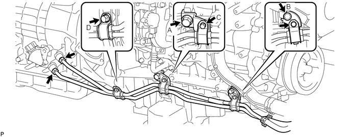
Temporarily install the ends of the 2 oil cooler tubes to each oil cooler tube union by hand.
Close the 3 No. 2 flexible hose clamps and install the 3 bolts.
- Torque:
- for bolt C : 5.5 N*m (56 kgf*cm, 49 in.*lbf)
- for bolt D : 14 N*m (143 kgf*cm, 10 ft.*lbf)
Using a union nut wrench, tighten the inlet and outlet tubes.
- Torque:
- 34 N*m (347 kgf*cm, 25 ft.*lbf)
- NOTICE:
-
Use the formula to calculate special torque values for situations where a union nut wrench is combined with a torque wrench (See page General>INTRODUCTION>REPAIR INSTRUCTION>PRECAUTION).
32941
2.INSTALL NO. 1 OIL COOLER INLET HOSE AND NO. 1 OIL COOLER OUTLET HOSE
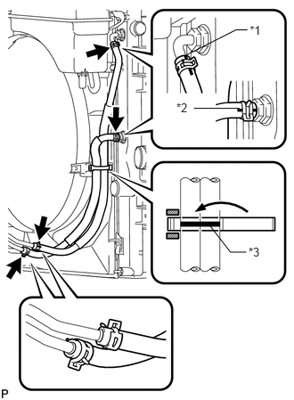
Connect the No. 1 oil cooler inlet hose and No. 1 oil cooler outlet hose to the No. 1 oil cooler inlet tube and No. 1 oil cooler outlet tube.
| *1 | Blue Paint Mark |
| *2 | Pink Paint Mark |
| *3 | White Paint Mark |
Connect the 2 hoses to the radiator to install them, and then pass the 2 hoses through the No. 1 flexible hose clamp and close the clamp.
- NOTICE:
- ·
When connecting the hoses to the tube, support the tube by hand and be careful to prevent the tube from being deformed.
·Make sure the paint marks and pinching portion of each clip are facing the directions shown in the illustration.
3.ADJUST AUTOMATIC TRANSMISSION FLUID LEVEL
Adjust automatic transmission fluid level (See page Drivetrain>A750F (AUTOMATIC TRANSMISSION / TRANSAXLE)>AUTOMATIC TRANSMISSION FLUID>ADJUSTMENT).
53736
4.INSTALL FRONT FENDER APRON SEAL RH
53736B
5.INSTALL NO. 1 FRONT FENDER APRON TO FRAME SEAL RH
51405A
6.INSTALL NO. 1 ENGINE UNDER COVER SUB-ASSEMBLY
51450
7.INSTALL REAR ENGINE UNDER COVER ASSEMBLY