1KD-FTV INTAKE / EXHAUST EXHAUST MANIFOLD W/ TURBOCHARGER INSTALLATION
PROCEDURE

 16027
1.INSTALL NO. 1 TURBO WATER PIPE SUB-ASSEMBLY
Install a new gasket and the No. 1 turbo water pipe sub-assembly and bolt to the turbocharger sub-assembly with the 2 nuts.
- Torque:
- for bolt : 8.0 N*m (82 kgf*cm, 71 in.*lbf)
- for nut : 12 N*m (122 kgf*cm, 9 ft.*lbf)
17141
2.INSTALL EXHAUST MANIFOLD WITH TURBOCHARGER SUB-ASSEMBLY
Temporarily install a new gasket and the turbocharger sub-assembly to the exhaust manifold with 3 new nuts.
- HINT:
-
It is easier to install the turbo oil inlet pipe sub-assembly if the 3 nuts are only loosely installed.
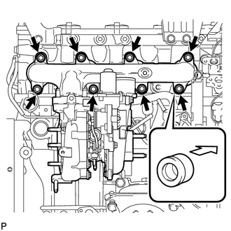
Set a new gasket on the engine and install the exhaust manifold with turbocharger sub-assembly, the 8 collars and the 8 plate washers with 8 new nuts.
- Torque:
- 40 N*m (408 kgf*cm, 30 ft.*lbf)
- NOTICE:
-
Install the collars so that the side with the smaller external diameter faces the exhaust manifold.
Temporarily install the turbo oil inlet pipe sub-assembly to the turbocharger sub-assembly.
- HINT:
-
Before installing the turbo oil inlet pipe sub-assembly, clean it.
Install a new gasket and the turbo oil inlet pipe sub-assembly with the 2 nuts, but only loosely install the nuts.
- NOTICE:
-
The notch (narrow part) of the gasket must face the engine.
Install a new gasket and the turbo oil inlet pipe sub-assembly with the 2 bolts, but only loosely install the bolts.
- NOTICE:
-
The claws of the gasket must face the pipe.
Install a new gasket and the turbo oil inlet pipe sub-assembly with the union bolt, but only loosely install the union bolt.
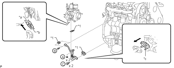
| *1 | Gasket | - | - |
| *a | Wide | *b | Narrow |
| *c | Claw | - | - |

|
Outside | - | - |
Temporarily install the turbocharger stay to the turbocharger sub-assembly and cylinder block sub-assembly with the 2 bolts and nut.
Tighten the 3 nuts of the turbocharger sub-assembly.
- Torque:
- 52 N*m (530 kgf*cm, 38 ft.*lbf)
Tighten the 2 nuts labeled A.
- Torque:
- 13 N*m (133 kgf*cm, 10 ft.*lbf)
Tighten the union bolt labeled B.
- Torque:
- 33 N*m (337 kgf*cm, 24 ft.*lbf)
Tighten the 2 bolts labeled C.
- Torque:
- 12 N*m (122 kgf*cm, 9 ft.*lbf)
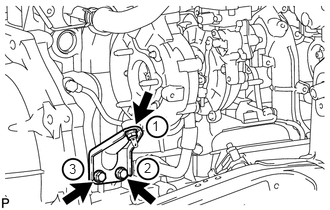
Tighten the 2 bolts and nut of the turbocharger stay in the order shown in the illustration.
- Torque:
- 38 N*m (387 kgf*cm, 28 ft.*lbf)
17291
3.INSTALL TURBINE OUTLET ELBOW
Install a new gasket and the turbine outlet elbow to the turbocharger sub-assembly with the 3 nuts.
- Torque:
- 39 N*m (398 kgf*cm, 29 ft.*lbf)
16284
4.CONNECT NO. 1 TURBO WATER HOSE
Connect the No. 1 turbo water hose to the No. 1 turbo water pipe sub-assembly, and slide the clamp to secure the hose.
17167
5.INSTALL NO. 1 EXHAUST MANIFOLD HEAT INSULATOR
Temporarily install the No. 1 exhaust manifold heat insulator to the exhaust manifold with the bolt.
17271
6.INSTALL NO. 1 TURBO INSULATOR
Temporarily install the No. 1 turbo insulator to the turbocharger sub-assembly with the 2 bolts.
Tighten the bolt of the No. 1 exhaust manifold heat insulator and the 2 bolts of the No. 1 turbo insulator.
- Torque:
- 12 N*m (122 kgf*cm, 9 ft.*lbf)
17274
7.INSTALL COMPRESSOR INLET ELBOW
Install a new gasket and the compressor inlet elbow with the 2 nuts.
- Torque:
- 19 N*m (194 kgf*cm, 14 ft.*lbf)
Connect the No. 2 turbo water hose and No. 3 turbo water hose to the No. 1 turbo water pipe sub-assembly, and slide the clamp to secure the hose.
Connect the No. 3 turbo water hose and No. 3 turbo water hose to the No. 2 water by-pass pipe, and slide the clamp to secure the hose.
Connect the 2 connectors and attach the wire harness clamp.
Install the wire harness bracket to the water inlet with the bolt.
- Torque:
- 8.0 N*m (82 kgf*cm, 71 in.*lbf)
Attach the 3 wire harness clamps.
11409
8.INSTALL ENGINE OIL LEVEL DIPSTICK GUIDE
Install a new O-ring to the engine oil level dipstick guide.
Apply a small amount of clean engine oil to the O-ring.
Install the engine oil level dipstick guide to the cylinder block sub-assembly with the 2 bolts.
- Torque:
- 8.0 N*m (82 kgf*cm, 71 in.*lbf)
Install the engine oil level dipstick.
12229
9.INSTALL VENTILATION PIPE
Connect the 2 ventilation hoses and install the ventilation pipe to the cylinder head cover to the cylinder head sub-assembly with the bolt.
- Torque:
- 18 N*m (184 kgf*cm, 13 ft.*lbf)
Type A
Connect the No. 3 turbo water hose and No. 4 turbo water hose to the ventilation pipe, and slide the 2 clamps to secure the hose.
88431
10.INSTALL NO. 1 COMPRESSOR MOUNTING BRACKET
12511C
11.INSTALL GENERATOR BRACKET
27020
12.INSTALL GENERATOR ASSEMBLY
88320
13.CONNECT COOLER COMPRESSOR ASSEMBLY (w/ Air Conditioning System)
87101
14.INSTALL NO. 1 VISCOUS HEATER BRACKET SUB-ASSEMBLY (for Cold Area Specification Vehicles)
87120G
15.INSTALL VISCOUS WITH MAGNET CLUTCH HEATER ASSEMBLY (for Cold Area Specification Vehicles)
17275A
16.INSTALL COMPRESSOR OUTLET ELBOW
Install the compressor outlet elbow with the 2 bolts and tighten the hose clamp.
- Torque:
- for bolt : 20 N*m (204 kgf*cm, 15 ft.*lbf)
- for hose clamp : 6.5 N*m (66 kgf*cm, 58 in.*lbf)
Install the wire harness bracket with the bolt.
- Torque:
- 8.0 N*m (82 kgf*cm, 71 in.*lbf)
Attach the 3 wire harness clamps.
17341K
17.INSTALL NO. 1 AIR HOSE
18.INSTALL AIR CLEANER CASE SUB-ASSEMBLY
Install the air cleaner case sub-assembly with the 3 bolts.
- Torque:
- 12 N*m (122 kgf*cm, 9 ft.*lbf)
17801
19.INSTALL AIR CLEANER FILTER ELEMENT SUB-ASSEMBLY
17705
20.INSTALL AIR CLEANER CAP SUB-ASSEMBLY
Attach the 4 clamps to install the air cleaner cap sub-assembly.
except Cold Area Specification Vehicles:
Attach the 2 clamps and connect the mass air flow meter connector.
for Cold Area Specification Vehicles:
Attach the 3 clamps and connect the mass air flow meter connector.
17881
21.INSTALL NO. 1 AIR CLEANER HOSE
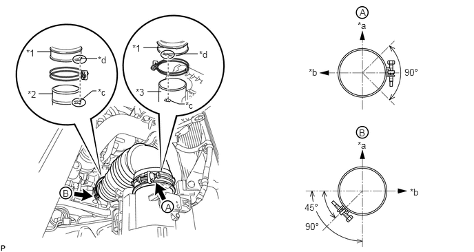
| *1 | No. 1 Air Cleaner Hose | *2 | Compressor Inlet Elbow |
| *3 | Air Cleaner Cap | - | - |
| *a | Upper Side | *b | Front Side of Vehicle |
| *c | Protrusion | *d | Groove |
Install the No. 1 air cleaner hose with the 2 hose clamps.
- NOTICE:
- ·
When installing the No. 1 air cleaner hose, align the protrusion of the No. 1 air cleaner hose with the protrusion of the compressor inlet elbow as shown in the illustration.
·When installing the No. 1 air cleaner hose, align the groove of the No. 1 air cleaner hose with the protrusion of the air cleaner cap as shown in the illustration.
Tighten the 2 hose clamps.
- Torque:
- 5.0 N*m (51 kgf*cm, 44 in.*lbf)
- NOTICE:
-
When tightening the 2 hose clamps, make sure that they are positioned as shown in the illustration.
16361A
22.INSTALL FAN AND GENERATOR V BELT
87452A
23.INSTALL FRONT HEATER BRACKET (for Cold Area Specification Vehicles)
53292A
24.INSTALL UPPER RADIATOR SUPPORT SEAL
53736B
25.INSTALL FRONT NO. 1 FENDER APRON TO FRAME SEAL RH
Install the front No. 1 fender apron to frame seal RH with the 5 clips.
53736
26.INSTALL FRONT FENDER APRON SEAL RH
Install the front fender apron seal RH with the 4 clips.
17410
27.INSTALL FRONT EXHAUST PIPE ASSEMBLY
28.CONNECT CABLE TO NEGATIVE BATTERY TERMINAL
- NOTICE:
-
When disconnecting the cable, some systems need to be initialized after the cable is reconnected (See page General>INTRODUCTION>REPAIR INSTRUCTION>INITIALIZATION).
29.ADD ENGINE COOLANT
30.INSPECT FOR COOLANT LEAK
31.INSPECT FOR OIL LEAK
32.INSPECT FOR EXHAUST GAS LEAK
51405A
33.INSTALL NO. 1 ENGINE UNDER COVER SUB-ASSEMBLY
52129B
34.INSTALL FRONT BUMPER LOWER COVER