REAR SUSPENSION REAR UPPER ARM INSTALLATION
CAUTION / NOTICE / HINT
- HINT:
- ·
Use the same procedure for the RH and LH sides.
·The procedure listed below is for the LH side.
·A bolt without a torque specification is shown in the standard bolt chart (See page General>SPECIFICATIONS>STANDARD BOLT>SPECIFIED TORQUE FOR STANDARD BOLTS).
PROCEDURE

 48790
1.TEMPORARILY INSTALL REAR UPPER CONTROL ARM ASSEMBLY LH
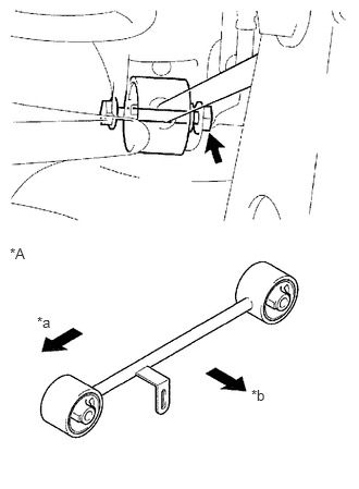
Temporarily install the upper control arm assembly and washer with the nut and bolt.
| *A | w/ Air Suspension |
| *a | Front |
| *b | Outer Side |
- HINT:
-
If the vehicle is equipped with an air suspension, install the rear upper control arm in the direction shown in the illustration.
Temporarily install the upper control arm assembly to the rear axle housing with the nut and washer and bolt.
89408D
2.CONNECT REAR HEIGHT CONTROL SENSOR LINK (w/ Air Suspension)
Connect the height control sensor link sub-assembly (See page Suspension>SUSPENSION CONTROL>HEIGHT CONTROL SENSOR>INSTALLATION).
3.INSTALL REAR WHEEL
- Torque:
- for Aluminum Wheel : 103 N*m (1050 kgf*cm, 76 ft.*lbf)
- for Steel Wheel : 112 N*m (1137 kgf*cm, 82 ft.*lbf)
4.STABILIZE SUSPENSION
48790
5.TIGHTEN REAR UPPER CONTROL ARM ASSEMBLY LH
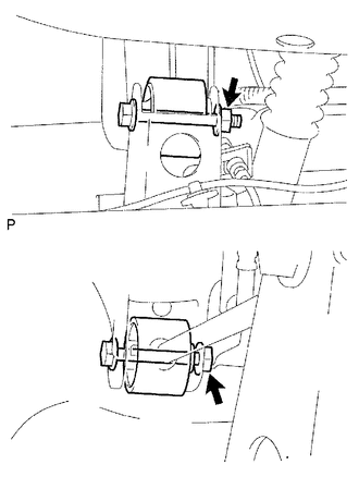
Tighten the 2 nuts.
- Torque:
- 80 N*m (816 kgf*cm, 59 ft.*lbf)
- HINT:
-
Turn the nut while holding the bolt.