BRAKE CONTROL / DYNAMIC CONTROL SYSTEMS VEHICLE STABILITY CONTROL SYSTEM(for Hydraulic Brake Booster) Skid Control Buzzer Circuit
DESCRIPTION
The skid control buzzer sounds upon receiving a signal from the skid control ECU.
WIRING DIAGRAM
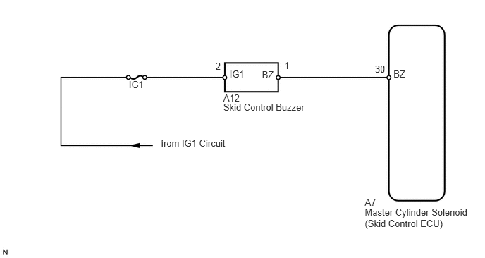
CAUTION / NOTICE / HINT
- NOTICE:
-
When replacing the master cylinder solenoid, perform calibration (See page Brake>BRAKE CONTROL / DYNAMIC CONTROL SYSTEMS>VEHICLE STABILITY CONTROL SYSTEM (for Hydraulic Brake Booster)>CALIBRATION).
PROCEDURE
Turn the ignition switch off.
Connect the intelligent tester to the DLC3.
Turn the ignition switch to ON.
Turn the intelligent tester on.
Enter the following menus: Chassis / ABS/VSC/TRC / Active Test.
| Tester Display | Test Part | Control Range | Diagnostic Note |
|---|---|---|---|
| DSS Signal Buzzer | Skid control buzzer | Buzzer ON/OFF | The buzzer can be heard. |
Check that the skid control buzzer sounds/stops when turning the skid control buzzer on/off by using the intelligent tester.
| Result | Proceed to |
|---|---|
| Buzzer does not sound or sounds constantly | A |
| Buzzer sounds/stops | B |
A
B
(See pageGeneral>INTRODUCTION>HOW TO TROUBLESHOOT ECU CONTROLLED SYSTEMS>HOW TO PROCEED WITH TROUBLESHOOTING)
Disconnect the A12 skid control buzzer connector.
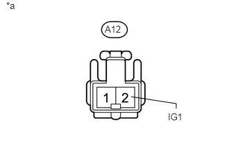
Measure the voltage according to the value(s) in the table below.
- Standard Voltage:
Tester Connection Switch Condition Specified Condition A12-2 (IG1) - Body ground Ignition switch ON 11 to 14 V
| *a | Front view of wire harness connector
(to Skid Control Buzzer) |
OK
NG
Remove the skid control buzzer (See page Brake>BRAKE CONTROL / DYNAMIC CONTROL SYSTEMS>SKID CONTROL BUZZER>REMOVAL).
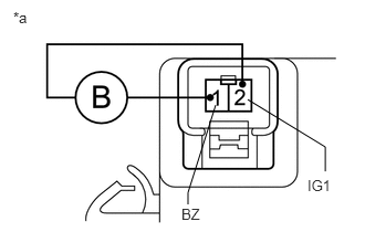
Apply battery voltage to the skid control buzzer, and check that the buzzer sounds.
- OK:
Measurement Condition Specified Condition Battery positive (+) voltage - Terminal 2 (IG1) Skid control buzzer sounds Battery negative (-) voltage - Terminal 1 (BZ)
| *a | Component without harness connected
(Skid Control Buzzer) |
OK
NG
Disconnect the A7 skid control ECU connector.
Disconnect the A12 skid control buzzer connector.
Measure the resistance according to the value(s) in the table below.
- Standard Resistance:
Tester Connection Condition Specified Condition A7-30 (BZ) - A12-1 (BZ) Always Below 1 Ω A7-30 (BZ) - Body ground Always 10 kΩ or higher
| Result | Proceed to |
|---|---|
| NG | A |
| OK (for LHD) | B |
| OK (for RHD) | C |
A
B
C