Home › Audio / Visual / Telematics › NAVIGATION / MULTI INFO DISPLAY › NAVIGATION SYSTEM (for Navigation Receiver Type) › 2015.06–2020.08
RM27T0E _56 Audio / Visual / Telematics _053721 NAVIGATION / MULTI INFO DISPLAY _0260991 NAVIGATION SYSTEM(for Navigation Receiver Type) J

NAVIGATION / MULTI INFO DISPLAY  NAVIGATION SYSTEM(for Navigation Receiver Type)  Microphone Circuit between Microphone and Navigation Receiver Assembly  


DESCRIPTION

This circuit sends a microphone signal from the telephone microphone assembly to the navigation receiver assembly.

It also supplies power from the navigation receiver assembly to the telephone microphone assembly.

WIRING DIAGRAM
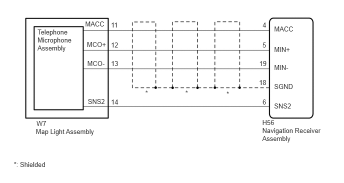
B360077E04
0.746,2.653 2.562,2.850 1.817,0.197 10 Map Light Assembly 0.781,0.587 1.556,1.270 0.775,0.683 10 Telephone Microphone Assembly 1.811,0.847 2.259,1.006 0.448,0.159 10 MCO+ 1.818,1.237 2.231,1.396 0.413,0.159 10 MCO- 1.774,0.422 2.231,0.581 0.456,0.159 10 MACC 4.718,1.88 5.330,2.039 0.613,0.159 10 * 3.026,1.852 3.639,2.011 0.613,0.159 10 * 0.287,3.344 2.678,3.503 2.391,0.159 10 *: Shielded 2.312,2.038 2.560,2.197 0.249,0.159 10 14 2.312,0.855 2.523,1.014 0.211,0.159 10 12 2.312,1.244 2.523,1.403 0.211,0.159 10 13 2.312,0.438 2.560,0.597 0.249,0.159 10 11 5.469,2.038 5.597,2.197 0.128,0.159 10 6 5.396,1.637 5.584,1.796 0.188,0.159 10 18 5.469,0.855 5.579,1.014 0.110,0.159 10 5 5.401,1.244 5.584,1.403 0.183,0.159 10 19 5.469,0.438 5.597,0.597 0.128,0.159 10 4 5.464,2.637 6.748,2.995 1.284,0.358 10 Navigation Receiver Assembly 0.76,2.487 1.244,2.698 0.484,0.211 10 W7 5.464,2.473 5.887,2.648 0.423,0.175 10 H56 5.711,0.95 6.151,1.109 0.441,0.159 10 MIN+ 5.711,1.327 6.151,1.486 0.441,0.159 10 MIN- 5.711,1.724 6.195,1.884 0.485,0.159 10 SGND 5.711,0.525 6.151,0.684 0.441,0.159 10 MACC 1.83,2.031 2.231,2.190 0.401,0.159 10 SNS2 5.711,2.122 6.151,2.281 0.441,0.159 10 SNS2 3.86,1.852 4.473,2.011 0.613,0.159 10 *

CAUTION / NOTICE / HINT

HINT:

When replacing the navigation receiver assembly, it is necessary to perform the vehicle contract setting for Connected Services (w/ Connected Services Function).


PROCEDURE
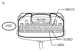
1.CHECK NAVIGATION RECEIVER ASSEMBLY
a.
U170702E03
2.052,1.302 2.167,1.896 2.167,1.896 2.396,1.896 false 2.177,1.302 2.406,1.667 2.406,1.667 2.635,1.667 false 2.198,1.094 2.448,0.406 2.448,0.406 2.719,0.406 false 2.417,1.802 2.781,1.979 0.365,0.177 10 false MIN- 2.656,1.573 3.104,1.75 0.448,0.177 10 false SGND 2.74,0.313 3.188,0.49 0.448,0.177 10 false MACC 0.063,0.042 0.302,0.219 0.24,0.177 10 false *a 0.24,1 0.729,1.177 0.49,0.177 10 false H56

Measure the resistance according to the value(s) in the table below.

Standard Resistance:
Tester Connection Condition Specified Condition
H56-19 (MIN-) - Body ground Always Below 1 Ω
H56-18 (SGND) - Body ground Always Below 1 Ω


b.

Measure the voltage according to the value(s) in the table below.

Standard Voltage:
Tester Connection Switch Condition Specified Condition
H56-4 (MACC) - Body ground Engine switch on (ACC) 4.75 to 5.25 V


Text in Illustration
*a Component with harness connected
(Navigation Receiver Assembly)


OK

2.CHECK HARNESS AND CONNECTOR (NAVIGATION RECEIVER ASSEMBLY - ROOF CONSOLE BOX ASSEMBLY)

NG

2.CHECK HARNESS AND CONNECTOR (NAVIGATION RECEIVER ASSEMBLY - ROOF CONSOLE BOX ASSEMBLY)
a.

Disconnect the H56 navigation receiver assembly connector.


b.

Disconnect the W7 roof console box assembly connector.


c.

Measure the resistance according to the value(s) in the table below.

Standard Resistance:
Tester Connection Condition Specified Condition
H56-4 (MACC) - W7-11 (MACC) Always Below 1 Ω
H56-5 (MIN+) - W7-12 (MCO+) Always Below 1 Ω
H56-19 (MIN-) - W7-13 (MCO-) Always Below 1 Ω
H56-6 (SNS2) - W7-14 (SNS2) Always Below 1 Ω
H56-4 (MACC) - Body ground Always 10 kΩ or higher
H56-5 (MIN+) - Body ground Always 10 kΩ or higher
H56-19 (MIN-) - Body ground Always 10 kΩ or higher
H56-18 (SGND) - Body ground Always 10 kΩ or higher
H56-6 (SNS2) - Body ground Always 10 kΩ or higher


OK

3.CHECK TELEPHONE MICROPHONE ASSEMBLY

NG

REPAIR OR REPLACE HARNESS OR CONNECTOR

3.CHECK TELEPHONE MICROPHONE ASSEMBLY
a.

Replace the telephone microphone assembly with a known good one (See page Audio / Visual / Telematics>AUDIO / VIDEO>MICROPHONE AMPLIFIER>REMOVAL).


b.

Check if the same problem occurs again.

OK:

Malfunction disappears.


OK

END (TELEPHONE MICROPHONE ASSEMBLY IS DEFECTIVE)

NG