Home › Power Source / Network › NETWORKING › CAN COMMUNICATION SYSTEM(for LHD with Entry and Start System) › 2015.06–2017.08
RM27T0E _57 Power Source / Network _053729 NETWORKING _0261031 CAN COMMUNICATION SYSTEM(for LHD with Entry and Start System) C

NETWORKING  CAN COMMUNICATION SYSTEM(for LHD with Entry and Start System)  U1002  Lost Communication with Gateway Module (Power Management2)  


DESCRIPTION

·

The power management control ECU stores this DTC when no signals can be received from the ECUs that have been memorized as those connected to the power management bus.

·

When the power management control ECU receives a response signal from the ECUs connected to the power management bus, the power management control ECU recognizes and memorizes that the ECU is connected to the power management bus. Based on this memorized data, the power management control ECU monitors for malfunctions in the ECUs connected to the power management bus when communicating with those ECUs. If the power management control ECU cannot receive response signals from the ECUs that have been memorized as those connected to the power management bus, the power management control ECU determines that a malfunction exists.

·

If 2 or more DTCs are output during the DTC check, one side of the CAN branch wire may be open (one side of the CANH [branch wire]/CANL [branch wire] of the ECU and/or sensor is open).


DTC Code DTC Detection Condition Trouble Area
U1002 Lost communication with the gateway module (Power Management2).
·

Power management bus circuit

·

Air conditioning amplifier assembly branch wire or connector

·

Power management control ECU main wire or connector

·

ECM main wire or connector

·

Air conditioning amplifier assembly

·

Power management control ECU

·

ECM

·

No. 1 junction connector


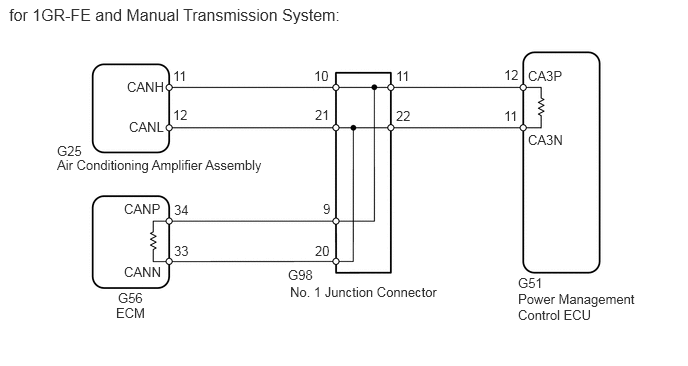
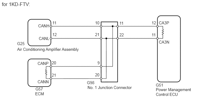
WIRING DIAGRAM

C215389E18
1.813,2.531 1.99,2.698 0.177,0.167 10 false 33 1.813,2.104 1.99,2.26 0.177,0.156 10 false 34 5.396,2.865 5.719,3.042 0.323,0.177 10 false G51 3,2.781 3.323,2.958 0.323,0.177 10 false G98 3.021,2.958 4.635,3.135 1.615,0.177 10 false No. 1 Junction Connector 1.208,3.177 1.563,3.354 0.354,0.177 10 false ECM 1.344,1.24 1.74,1.417 0.396,0.177 10 false CANL 1.323,0.823 1.75,1 0.427,0.177 10 false CANH 1.802,1.115 2.115,1.292 0.313,0.177 10 false 12 1.802,0.708 2.115,0.885 0.313,0.177 10 false 11 0.094,0.052 4.563,0.281 4.469,0.229 12 false for 1GR-FE and Manual Transmission System: 0.594,1.635 2.844,1.813 2.25,0.177 10 false Air Conditioning Amplifier Assembly 1.292,2.094 1.729,2.271 0.438,0.177 10 false CANP 5.5,0.708 5.938,0.885 0.438,0.177 10 false CA3P 3.365,2.094 3.469,2.271 0.104,0.177 10 false 9 3.281,2.531 3.458,2.708 0.177,0.177 10 false 20 3.271,0.708 3.458,0.885 0.188,0.177 10 false 10 3.281,1.115 3.458,1.292 0.177,0.177 10 false 21 4.125,0.708 4.323,0.885 0.198,0.177 10 false 11 4.125,1.125 4.302,1.302 0.177,0.177 10 false 22 5.25,0.698 5.427,0.875 0.177,0.177 10 false 12 5.25,1.125 5.427,1.302 0.177,0.177 10 false 11 1.292,2.75 1.729,2.927 0.438,0.177 10 false CANN 5.5,1.375 5.938,1.552 0.438,0.177 10 false CA3N 5.396,3.031 6.688,3.427 1.292,0.396 10 false Power Management Control ECU 1.229,3.021 1.552,3.198 0.323,0.177 10 false G56 0.594,1.49 0.917,1.667 0.323,0.177 10 false G25

C215389E19
1.792,2.094 1.969,2.26 0.177,0.167 10 false 20 1.792,2.521 1.969,2.677 0.177,0.156 10 false 21 5.396,2.865 5.719,3.042 0.323,0.177 10 false G51 3.01,2.781 3.333,2.958 0.323,0.177 10 false G98 3.031,2.948 4.646,3.125 1.615,0.177 10 false No. 1 Junction Connector 1.219,3.167 1.573,3.344 0.354,0.177 10 false ECM 1.344,1.25 1.74,1.427 0.396,0.177 10 false CANL 1.323,0.813 1.75,0.99 0.427,0.177 10 false CANH 1.813,1.115 2.125,1.292 0.313,0.177 10 false 12 1.813,0.708 2.125,0.885 0.313,0.177 10 false 11 0.063,0.042 1.104,0.292 1.042,0.25 12 false for 1KD-FTV: 0.594,1.625 2.844,1.802 2.25,0.177 10 false Air Conditioning Amplifier Assembly 1.302,2.115 1.74,2.292 0.438,0.177 10 false CANP 5.5,0.708 5.938,0.885 0.438,0.177 10 false CA3P 3.375,2.094 3.479,2.271 0.104,0.177 10 false 9 3.292,2.51 3.469,2.688 0.177,0.177 10 false 20 3.292,0.708 3.479,0.885 0.188,0.177 10 false 10 3.292,1.115 3.469,1.292 0.177,0.177 10 false 21 4.135,0.719 4.333,0.896 0.198,0.177 10 false 11 4.135,1.125 4.313,1.302 0.177,0.177 10 false 22 5.25,0.708 5.427,0.885 0.177,0.177 10 false 12 5.25,1.125 5.427,1.302 0.177,0.177 10 false 11 1.302,2.75 1.74,2.927 0.438,0.177 10 false CANN 5.5,1.375 5.938,1.552 0.438,0.177 10 false CA3N 5.396,3.021 6.688,3.417 1.292,0.396 10 false Power Management Control ECU 1.229,3 1.552,3.177 0.323,0.177 10 false G57 0.594,1.427 0.917,1.604 0.323,0.177 10 false G25

CAUTION / NOTICE / HINT

NOTICE:

Inspect the fuses for circuits related to this system before performing the following inspection procedure.


HINT:

Operating the engine switch, any switches or any doors triggers related ECU and sensor communication with the CAN, which causes resistance variation.


PROCEDURE

1.DISCONNECT CABLE FROM NEGATIVE BATTERY TERMINAL
a.

Disconnect the cable from the negative (-) battery terminal before measuring the resistances of the CAN main wire and CAN branch wire.

CAUTION:

Wait at least 90 seconds after disconnecting the cable from the negative (-) battery terminal to disable the airbag system.


NOTICE:
·

After turning the engine switch off, waiting time may be required before disconnecting the cable from the battery terminal. Therefore, make sure to read the disconnecting the cable from the battery terminal notice before proceeding with work (See page General>INTRODUCTION>REPAIR INSTRUCTION>PRECAUTION).

·

When disconnecting the cable, some systems need to be initialized after the cable is reconnected (See page General>INTRODUCTION>REPAIR INSTRUCTION>INITIALIZATION).


NEXT
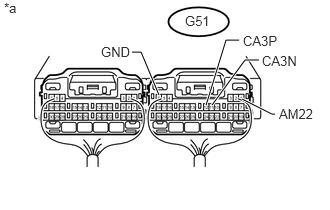
2.CHECK CAN BUS WIRE (MAIN WIRE FOR DISCONNECTION, BUS LINE FOR SHORT CIRCUIT)
a.
U148248E04
2.208,1.094 2.552,0.625 2.552,0.625 2.698,0.625 true 1.656,0.99 1.469,0.542 1.469,0.542 1.375,0.542 true 2.146,1.094 2.354,0.417 2.354,0.417 2.49,0.417 true 2.521,1.031 2.833,1.188 2.833,1.188 2.865,1.188 true 0.042,0 0.219,0.167 0.177,0.167 10 false *a 1.927,0.135 2.219,0.302 0.292,0.167 10 false G51 2.906,1.104 3.302,1.271 0.396,0.167 10 false AM22 1.052,0.458 1.396,0.625 0.344,0.167 10 false GND 2.729,0.552 3.188,0.729 0.458,0.177 10 false CA3N 2.531,0.344 3.042,0.521 0.51,0.177 10 false CA3P

Measure the resistance according to the value(s) in the table below.

Standard Resistance:
Tester Connection Switch Condition Specified Condition Resistance: Malfunction
G51-12 (CA3P) - G51-11 (CA3N) Engine switch off 54 to 69 Ω Below 53 Ω: Short in line
G51-12 (CA3P) - G51-11 (CA3N) Engine switch off 54 to 69 Ω Higher than 70 Ω: Open in CAN main bus line
G51-12 (CA3P) - G51-1 (AM22) Engine switch off 6 kΩ or higher Below 6 kΩ: +B short
G51-11 (CA3N) - G51-1 (AM22) Engine switch off 6 kΩ or higher Below 6 kΩ: +B short
G51-12 (CA3P) - G51-6 (GND) Engine switch off 200 Ω or higher Below 200 Ω: Ground short
G51-11 (CA3N) - G51-6 (GND) Engine switch off 200 Ω or higher Below 200 Ω: Ground short


Text in Illustration
*a Component with harness connected
(Power Management Control ECU)

Result
Result Proceed to
NG
·

Open in CAN main bus line


A
NG
·

Short in line

·

+B short

·

Ground short


B
OK C


A

3.CHECK FOR OPEN IN CAN BUS MAIN WIRE (NO. 1 JUNCTION CONNECTOR - ECM)

B

9.CHECK FOR SHORT IN CAN BUS WIRES (NO. 1 JUNCTION CONNECTOR - AIR CONDITIONING AMPLIFIER ASSEMBLY)

C

18.CHECK HARNESS AND CONNECTOR (POWER MANAGEMENT CONTROL ECU - BATTERY AND GROUND)
3.CHECK FOR OPEN IN CAN BUS MAIN WIRE (NO. 1 JUNCTION CONNECTOR - ECM)
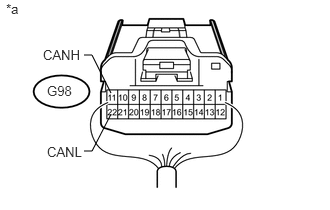
a.

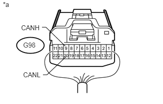
Disconnect the G98 No. 1 junction connector.

U148535E03
1.375,0.969 0.969,0.573 0.969,0.573 0.885,0.573 false 1.396,1.188 0.99,1.573 0.99,1.573 0.906,1.573 false 0.448,0.5 0.885,0.677 0.438,0.177 10 false CANH 0.49,0.865 0.781,1.042 0.292,0.177 10 false G98 0.063,0.01 0.271,0.188 0.208,0.177 10 false *a 0.49,1.49 0.927,1.667 0.438,0.177 10 false CANL

b.

Measure the resistance according to the value(s) in the table below.

Standard Resistance:
Tester Connection Switch Condition Specified Condition
G98-9 (CANH) - G98-20 (CANL) Engine switch off 108 to 132 Ω


Text in Illustration
*a Rear view of wire harness connector
(to No. 1 Junction Connector)


OK

4.CHECK FOR OPEN IN CAN BUS MAIN WIRE (NO. 1 JUNCTION CONNECTOR - POWER MANAGEMENT CONTROL ECU)

NG

5.CONNECT CONNECTOR
4.CHECK FOR OPEN IN CAN BUS MAIN WIRE (NO. 1 JUNCTION CONNECTOR - POWER MANAGEMENT CONTROL ECU)
a.
U148536E03
1.156,0.969 0.958,0.573 0.958,0.573 0.875,0.573 false 1.156,1.188 0.958,1.573 0.958,1.573 0.875,1.573 false 0.448,0.49 0.885,0.667 0.438,0.177 10 false CANH 0.49,0.865 0.813,1.042 0.323,0.177 10 false G98 0.49,1.5 0.927,1.677 0.438,0.177 10 false CANL 0.063,0.01 0.271,0.188 0.208,0.177 10 false *a

Measure the resistance according to the value(s) in the table below.

Standard Resistance:
Tester Connection Switch Condition Specified Condition
G98-11 (CANH) - G98-22 (CANL) Engine switch off 108 to 132 Ω


Text in Illustration
*a Rear view of wire harness connector
(to No. 1 Junction Connector)


OK

REPLACE NO. 1 JUNCTION CONNECTOR

NG

7.CONNECT CONNECTOR
5.CONNECT CONNECTOR
a.

Reconnect the G98 No. 1 junction connector.


NEXT

6.CHECK FOR OPEN IN CAN BUS MAIN WIRE (ECM - NO. 1 JUNCTION CONNECTOR)
a.

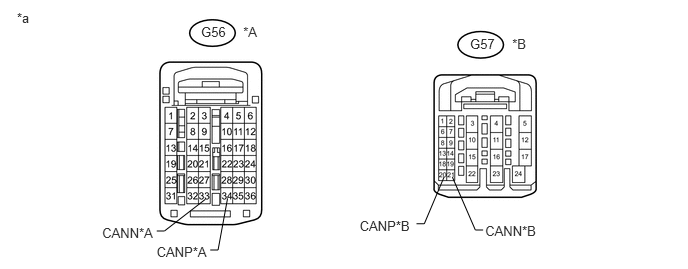
Disconnect the G56*1 or G57*2 ECM connector.

*1: for 1GR-FE and Manual Transmission System

*2: for 1KD-FTV

U170207E01
2.094,0.255 2.387,0.420 0.293,0.164 10 G56 2.533,0.255 2.825,0.420 0.293,0.164 10 *A 0.176,0.107 0.373,0.287 0.197,0.180 10 *a 1.631,2.537 2.236,2.695 0.605,0.159 10 CANP*A 1.064,2.343 1.666,2.500 0.602,0.158 10 CANN*A 2.139,2.075 1.712,2.406 1.712,2.406 1.632,2.406 false 2.37,2.066 2.271,2.604 2.271,2.604 2.19,2.604 false 3.746,2.273 4.351,2.432 0.605,0.159 10 CANP*B 5.054,2.324 5.656,2.482 0.602,0.158 10 CANN*B 4.625,1.844 4.419,2.331 4.419,2.331 4.338,2.331 false 4.712,1.844 4.951,2.395 4.951,2.395 5.032,2.395 false 4.896,0.379 5.189,0.543 0.293,0.164 10 G57 5.335,0.379 5.627,0.543 0.293,0.164 10 *B


Text in Illustration
*A for 1GR-FE and Manual Transmission System *B for 1KD-FTV
*a Front view of wire harness connector
(to ECM)
- -

b.

Measure the resistance according to the value(s) in the table below.

Standard Resistance:
for 1GR-FE and Manual Transmission System
Tester Connection Switch Condition Specified Condition
G56-34 (CANP) - G56-33 (CANN) Engine switch off 108 to 132 Ω

for 1KD-FTV
Tester Connection Switch Condition Specified Condition
G57-20 (CANP) - G57-21 (CANN) Engine switch off 108 to 132 Ω


Result
Result Proceed to
OK (for 1GR-FE) A
OK (for 1KD-FTV) B
NG C


A

B

C

REPAIR OR REPLACE CAN MAIN WIRE CONNECTED TO ECM (ECM - NO. 1 JUNCTION CONNECTOR)

7.CONNECT CONNECTOR
a.

Reconnect the G98 No. 1 junction connector.


NEXT
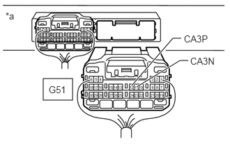
8.CHECK FOR OPEN IN CAN BUS MAIN WIRE (POWER MANAGEMENT CONTROL ECU - NO. 1 JUNCTION CONNECTOR)
a.
C348088E03
0.646,1.177 1.083,1.5 0.438,0.323 1.969,1.281 2.583,0.573 2.583,0.573 2.708,0.573 true 2.042,1.302 2.688,0.906 2.688,0.906 2.813,0.906 true 0.083,0.156 0.396,0.354 0.313,0.198 10 false *a 2.75,0.5 3.313,0.74 0.563,0.24 10 false CA3P 2.844,0.833 3.396,1.094 0.552,0.26 10 false CA3N 0.729,1.26 1.354,1.49 0.625,0.229 10 false G51

Disconnect the G51 power management control ECU connector.


b.

Measure the resistance according to the value(s) in the table below.

Standard Resistance:
Tester Connection Switch Condition Specified Condition
G51-12 (CA3P) - G51-11 (CA3N) Engine switch off 108 to 132 Ω


Text in Illustration
*a Rear view of wire harness connector
(to Power Management Control ECU)


OK

NG

REPAIR OR REPLACE CAN MAIN WIRE CONNECTED TO POWER MANAGEMENT CONTROL ECU (POWER MANAGEMENT CONTROL ECU - NO. 1 JUNCTION CONNECTOR)

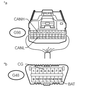
9.CHECK FOR SHORT IN CAN BUS WIRES (NO. 1 JUNCTION CONNECTOR - AIR CONDITIONING AMPLIFIER ASSEMBLY)
a.
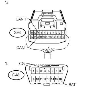
U148353E03
1.646,2.51 1.052,2.323 1.052,2.323 0.969,2.323 false 2.448,3.094 2.385,3.094 2.385,3.094 2.219,2.938 false 1.385,1.167 1.063,0.688 1.063,0.688 0.979,0.688 false 1.385,1.365 1.063,1.729 1.063,1.729 0.979,1.729 false 0.448,2.656 0.771,2.833 0.323,0.177 10 false G48 0.177,2.24 0.385,2.417 0.208,0.177 10 false *b 0.177,0 0.385,0.177 0.208,0.177 10 false *a 0.698,2.24 0.927,2.417 0.229,0.177 10 false CG 2.51,3.01 2.906,3.188 0.396,0.177 10 false BAT 0.573,0.615 1.01,0.792 0.438,0.177 10 false CANH 0.5,1.104 0.823,1.281 0.323,0.177 10 false G98 0.604,1.656 1.042,1.833 0.438,0.177 10 false CANL

Disconnect the G98 No. 1 junction connector.


b.

Measure the resistance according to the value(s) in the table below.

Standard Resistance:
Tester Connection Switch Condition Specified Condition
G98-10 (CANH) - G98-21 (CANL) Engine switch off 200 Ω or higher
G98-10 (CANH) - G48-4 (CG) Engine switch off 200 Ω or higher
G98-21 (CANL) - G48-4 (CG) Engine switch off 200 Ω or higher
G98-10 (CANH) - G48-16 (BAT) Engine switch off 6 kΩ or higher
G98-21 (CANL) - G48-16 (BAT) Engine switch off 6 kΩ or higher


Text in Illustration
*a Rear view of wire harness connector
(to No. 1 Junction Connector)
*b Front view of DLC3


OK

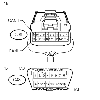
10.CHECK FOR SHORT IN CAN BUS WIRES (NO. 1 JUNCTION CONNECTOR - ECM)

NG

12.CONNECT CONNECTOR
10.CHECK FOR SHORT IN CAN BUS WIRES (NO. 1 JUNCTION CONNECTOR - ECM)
a.
U148354E03
1.625,2.542 1,2.344 1,2.344 0.917,2.344 false 2.469,3.063 2.396,3.063 2.396,3.063 2.219,2.948 false 1.385,1.167 1,0.698 1,0.698 0.917,0.698 false 1.406,1.354 1,1.74 1,1.74 0.917,1.74 false 0.448,2.667 0.771,2.844 0.323,0.177 10 false G48 0.135,2.26 0.344,2.438 0.208,0.177 10 false *b 0.135,0.021 0.344,0.198 0.208,0.177 10 false *a 0.646,2.26 0.875,2.438 0.229,0.177 10 false CG 2.49,2.99 2.885,3.167 0.396,0.177 10 false BAT 0.51,0.615 0.948,0.792 0.438,0.177 10 false CANH 0.5,1.104 0.823,1.281 0.323,0.177 10 false G98 0.542,1.667 0.979,1.844 0.438,0.177 10 false CANL

Measure the resistance according to the value(s) in the table below.

Standard Resistance:
Tester Connection Switch Condition Specified Condition
G98-9 (CANH) - G98-20 (CANL) Engine switch off 108 to 132 Ω
G98-9 (CANH) - G48-4 (CG) Engine switch off 200 Ω or higher
G98-20 (CANL) - G48-4 (CG) Engine switch off 200 Ω or higher
G98-9 (CANH) - G48-16 (BAT) Engine switch off 6 kΩ or higher
G98-20 (CANL) - G48-16 (BAT) Engine switch off 6 kΩ or higher


Text in Illustration
*a Rear view of wire harness connector
(to No. 1 Junction Connector)
*b Front view of DLC3


OK

11.CHECK FOR SHORT IN CAN BUS WIRES (NO. 1 JUNCTION CONNECTOR - POWER MANAGEMENT CONTROL ECU)

NG

14.CONNECT CONNECTOR
11.CHECK FOR SHORT IN CAN BUS WIRES (NO. 1 JUNCTION CONNECTOR - POWER MANAGEMENT CONTROL ECU)
a.
U148355E03
1.625,2.552 1,2.344 1,2.344 0.917,2.344 false 2.469,3.063 2.396,3.063 2.396,3.063 2.208,2.948 false 1.167,1.167 0.771,0.698 0.771,0.698 0.688,0.698 false 1.156,1.365 0.771,1.74 0.771,1.74 0.688,1.74 false 0.448,2.656 0.76,2.833 0.313,0.177 10 false G48 0.135,2.26 0.344,2.438 0.208,0.177 10 false *b 0.135,0.021 0.344,0.198 0.208,0.177 10 false *a 0.646,2.26 0.875,2.438 0.229,0.177 10 false CG 2.49,2.99 2.885,3.167 0.396,0.177 10 false BAT 0.281,0.615 0.719,0.792 0.438,0.177 10 false CANH 0.5,1.104 0.823,1.281 0.323,0.177 10 false G98 0.302,1.667 0.74,1.844 0.438,0.177 10 false CANL

Measure the resistance according to the value(s) in the table below.

Standard Resistance:
Tester Connection Switch Condition Specified Condition
G98-11 (CANH) - G98-22 (CANL) Engine switch off 108 to 132 Ω
G98-11 (CANH) - G48-4 (CG) Engine switch off 200 Ω or higher
G98-22 (CANL) - G48-4 (CG) Engine switch off 200 Ω or higher
G98-11 (CANH) - G48-16 (BAT) Engine switch off 6 kΩ or higher
G98-22 (CANL) - G48-16 (BAT) Engine switch off 6 kΩ or higher


Text in Illustration
*a Rear view of wire harness connector
(to No. 1 Junction Connector)
*b Front view of DLC3


OK

REPLACE NO. 1 JUNCTION CONNECTOR

NG

16.CONNECT CONNECTOR
12.CONNECT CONNECTOR
a.

Reconnect the G98 No. 1 junction connector.


NEXT
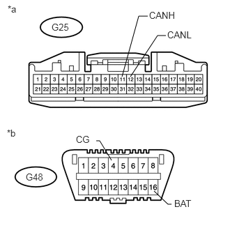
13.CHECK FOR SHORT IN CAN BUS WIRES (AIR CONDITIONING AMPLIFIER ASSEMBLY)
a.
U148534E06
2.302,2.854 2.51,3.052 2.51,3.052 2.563,3.052 false 1.667,2.396 1.49,2.104 1.49,2.104 1.438,2.104 false 1.948,1.146 2.354,0.531 2.354,0.531 2.479,0.531 false 1.823,1.146 2.073,0.24 2.073,0.24 2.208,0.24 false 0.104,1.906 0.302,2.073 0.198,0.167 10 false *b 0.385,2.563 0.698,2.74 0.313,0.177 10 false G48 1.135,2 1.365,2.177 0.229,0.177 10 false CG 2.604,2.958 2.958,3.135 0.354,0.177 10 false BAT 0.115,0.052 0.292,0.26 0.177,0.208 10 false *a 0.771,0.323 1.083,0.5 0.313,0.177 10 false G25 2.229,0.146 2.667,0.354 0.438,0.208 10 false CANH 2.5,0.438 2.938,0.646 0.438,0.208 10 false CANL

Disconnect the G25 air conditioning amplifier assembly connector.


b.

Measure the resistance according to the value(s) in the table below.

Standard Resistance:
Tester Connection Switch Condition Specified Condition
G25-11 (CANH) - G25-12 (CANL) Engine switch off 54 to 69 Ω
G25-11 (CANH) - G48-4 (CG) Engine switch off 200 Ω or higher
G25-12 (CANL) - G48-4 (CG) Engine switch off 200 Ω or higher
G25-11 (CANH) - G48-16 (BAT) Engine switch off 6 kΩ or higher
G25-12 (CANL) - G48-16 (BAT) Engine switch off 6 kΩ or higher


Text in Illustration
*a Front view of wire harness connector
(to Air Conditioning Amplifier Assembly)
*b Front view of DLC3


OK

REPLACE AIR CONDITIONING AMPLIFIER ASSEMBLY

NG

REPAIR OR REPLACE AIR CONDITIONING AMPLIFIER ASSEMBLY BRANCH WIRE OR CONNECTOR (CANH, CANL)

14.CONNECT CONNECTOR
a.

Reconnect the G98 No. 1 junction connector.


NEXT

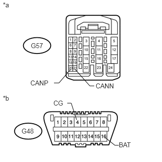
15.CHECK FOR SHORT IN CAN BUS WIRES (ECM)
a.

for 1GR-FE and Manual Transmission System:
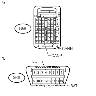
i.
U148681E02
1.646,2.542 1.51,2.188 1.51,2.188 1.427,2.188 false 2.229,2.917 2.438,3.083 2.438,3.083 2.521,3.083 false 1.76,1.458 2.104,1.74 2.104,1.74 2.198,1.74 false 1.552,1.458 1.729,1.979 1.729,1.979 1.813,1.979 false 0.677,0.938 0.958,1.115 0.281,0.177 10 false G56 0.458,2.688 0.781,2.865 0.323,0.177 10 false G48 0.063,0.021 0.271,0.198 0.208,0.177 10 false *a 0.063,2 0.271,2.177 0.208,0.177 10 false *b 1.135,2.104 1.375,2.281 0.24,0.177 10 false CG 2.521,2.99 2.958,3.167 0.438,0.177 10 false BAT 1.844,1.906 2.26,2.083 0.417,0.177 10 false CANP 2.219,1.656 2.667,1.823 0.448,0.167 10 false CANN

Disconnect the G56 ECM connector.


ii.

Measure the resistance according to the value(s) in the table below.

Standard Resistance:
Tester Connection Switch Condition Specified Condition
G56-34 (CANP) - G56-33 (CANN) Engine switch off 108 to 132 Ω
G56-34 (CANP) - G48-4 (CG) Engine switch off 200 Ω or higher
G56-33 (CANN) - G48-4 (CG) Engine switch off 200 Ω or higher
G56-34 (CANP) - G48-16 (BAT) Engine switch off 6 kΩ or higher
G56-33 (CANN) - G48-16 (BAT) Engine switch off 6 kΩ or higher


Text in Illustration
*a Rear view of wire harness connector
(to ECM)
*b Front view of DLC3


b.

for 1KD-FTV:

i.
U170213E02
1.5,1.469 1.25,1.76 1.25,1.76 1.146,1.76 false 1.583,1.458 1.906,1.823 1.906,1.823 2,1.823 false 1.625,2.542 1.51,2.188 1.51,2.188 1.427,2.188 false 2.229,2.917 2.438,3.083 2.438,3.083 2.521,3.083 false 0.656,0.885 0.948,1.052 0.292,0.167 10 false G57 0.646,1.677 1.063,1.833 0.417,0.156 10 false CANP 2.031,1.74 2.635,1.896 0.604,0.156 10 false CANN 0.458,2.698 0.781,2.875 0.323,0.177 10 false G48 0.063,0.021 0.271,0.198 0.208,0.177 10 false *a 0.063,2 0.271,2.177 0.208,0.177 10 false *b 1.135,2.104 1.375,2.281 0.24,0.177 10 false CG 2.521,2.99 2.958,3.167 0.438,0.177 10 false BAT

Disconnect the G57 ECM connector.


ii.

Measure the resistance according to the value(s) in the table below.

Standard Resistance:
Tester Connection Switch Condition Specified Condition
G57-20 (CANP) - G57-21 (CANN) Engine switch off 108 to 132 Ω
G57-20 (CANP) - G48-4 (CG) Engine switch off 200 Ω or higher
G57-21 (CANN) - G48-4 (CG) Engine switch off 200 Ω or higher
G57-20 (CANP) - G48-16 (BAT) Engine switch off 6 kΩ or higher
G57-21 (CANN) - G48-16 (BAT) Engine switch off 6 kΩ or higher


Text in Illustration
*a Front view of wire harness connector
(to ECM)
*b Front view of DLC3


Result
Result Proceed to
OK (for 1GR-FE) A
OK (for 1KD-FTV) B
NG C


A

B

C

REPAIR OR REPLACE ECM MAIN WIRE OR CONNECTOR (CANP, CANN)

16.CONNECT CONNECTOR
a.

Reconnect the G98 No. 1 junction connector.


NEXT
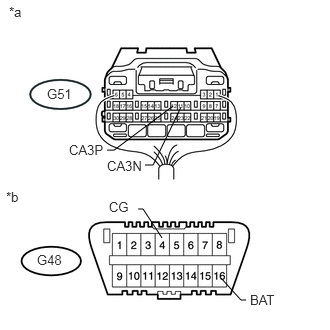
17.CHECK FOR SHORT IN CAN BUS WIRES (POWER MANAGEMENT CONTROL ECU)
a.
U148284E04
1.115,1.563 1.188,1.563 1.188,1.563 1.802,1.104 false 1.51,1.719 1.594,1.719 1.594,1.719 1.885,1.115 false 2.302,2.896 2.51,3.125 2.51,3.125 2.563,3.125 false 1.688,2.479 1.49,2.177 1.49,2.177 1.438,2.177 false 0.094,0.042 0.292,0.25 0.198,0.208 10 false *a 0.719,1.479 1.146,1.688 0.427,0.208 10 false CA3P 1.115,1.646 1.542,1.854 0.427,0.208 10 false CA3N 0.49,0.896 0.823,1.104 0.333,0.208 10 false G51 0.063,1.969 0.26,2.135 0.198,0.167 10 false *b 0.385,2.625 0.698,2.802 0.313,0.177 10 false G48 1.135,2.073 1.365,2.25 0.229,0.177 10 false CG 2.604,3.042 2.958,3.219 0.354,0.177 10 false BAT

Disconnect the G51 power management control ECU connector.


b.

Measure the resistance according to the value(s) in the table below.

Standard Resistance:
Tester Connection Switch Condition Specified Condition
G51-12 (CA3P) - G51-11 (CA3N) Engine switch off 108 to 132 Ω
G51-12 (CA3P) - G48-4 (CG) Engine switch off 200 Ω or higher
G51-11 (CA3N) - G48-4 (CG) Engine switch off 200 Ω or higher
G51-12 (CA3P) - G48-16 (BAT) Engine switch off 6 kΩ or higher
G51-11 (CA3N) - G48-16 (BAT) Engine switch off 6 kΩ or higher


Text in Illustration
*a Rear view of wire harness connector
(to Power Management Control ECU)
*b Front view of DLC3


OK

NG

REPAIR OR REPLACE POWER MANAGEMENT CONTROL ECU MAIN WIRE OR CONNECTOR (CA3P, CA3N)

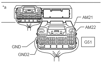
18.CHECK HARNESS AND CONNECTOR (POWER MANAGEMENT CONTROL ECU - BATTERY AND GROUND)
a.
C348088E04
2.719,1.25 3.156,1.573 0.438,0.323 2.354,1.167 2.583,0.573 2.583,0.573 2.708,0.573 true 2.427,1.167 2.688,0.906 2.688,0.906 2.813,0.906 true 1,1.833 1.156,1.833 1.156,1.833 1.427,1.208 true 0.729,1.573 0.885,1.573 0.885,1.573 1.365,1.208 true 0.083,0.156 0.396,0.354 0.313,0.198 10 false *a 2.75,0.5 3.313,0.74 0.563,0.24 10 false AM21 2.844,0.833 3.396,1.094 0.552,0.26 10 false AM22 0.396,1.49 1.021,1.719 0.625,0.229 10 false GND 0.604,1.75 1.229,1.979 0.625,0.229 10 false GND2 2.813,1.333 3.208,1.604 0.396,0.271 10 false G51

Connect the cable to the negative (-) battery terminal.

NOTICE:

When disconnecting the cable, some systems need to be initialized after the cable is reconnected (See page General>INTRODUCTION>REPAIR INSTRUCTION>INITIALIZATION).


b.

Disconnect the G51 power management control ECU connector.


c.

Measure the resistance according to the value(s) in the table below.

Standard Resistance:
Tester Connection Condition Specified Condition
G51-5 (GND2) - Body ground Always Below 1 Ω
G51-6 (GND) - Body ground Always Below 1 Ω


d.

Measure the voltage according to the value(s) in the table below.

Standard Voltage:
Tester Connection Condition Specified Condition
G51-1 (AM22) - Body ground Always 11 to 14 V
G51-2 (AM21) - Body ground Always 11 to 14 V


Text in Illustration
*a Rear view of wire harness connector
(to Power Management Control ECU)


OK

NG

REPAIR OR REPLACE HARNESS OR CONNECTOR