MIRROR (EXT) OUTER REAR VIEW MIRROR DISASSEMBLY
CAUTION / NOTICE / HINT
- HINT:
- ·
Use the same procedure for the and LH sides.
·The procedure listed below is for the LH side.
·w/ Side Monitor System:
When installing only the side television camera assembly, refer to TELEVISION CAMERA (for Side) (See page Audio / Visual / Telematics>PARK ASSIST / MONITORING>TELEVISION CAMERA (for Side)>INSTALLATION).
PROCEDURE

 87961
1.REMOVE OUTER REAR VIEW MIRROR GLASS
87945C
2.REMOVE OUTER MIRROR COVER LH
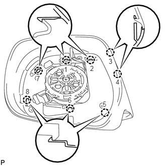
- HINT:
-
Be sure to detach the claws of the outer mirror cover in the order shown in the illustration.
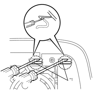
Using 2 screwdrivers, detach the 2 claws.
- HINT:
-
Tape the screwdriver tip before use.
| *1 | Protective Tape |
Insert a screwdriver into the slot as shown in the illustration and push on the outer mirror body to create a space between the outer mirror body and outer mirror cover.
- NOTICE:
-
Be careful not to break the ribs.
- HINT:
-
Tape the screwdriver tip before use.
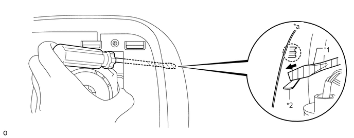
| *1 | Protective Tape | *2 | Rib |
| *a | Inner Side of Outer Mirror Cover | - | - |
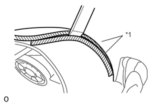
Insert a moulding remover into the space made between the outer mirror body and outer mirror cover.
- NOTICE:
-
Do not insert the moulding remover more than 4 mm (0.157 in.).
- HINT:
-
Tape the moulding remover before use.
| *1 | Protective Tape |
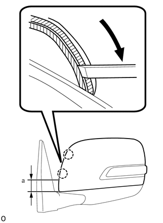
Slide the moulding remover downwards as shown in the illustration to detach the 2 claws.
- NOTICE:
- ·
Do not insert the moulding remover more than 4 mm (0.157 in.).
·Do not slide the moulding remover past the point approximately 40 mm (1.57 in.) from the bottom edge of the outer mirror cover as the outer mirror body will become damaged.
- Standard:
Area Specified Condition a 40.0 mm (1.57 in.)
Remove the moulding remover.
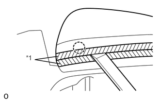
Insert a moulding remover between the outer mirror cover and outer mirror body as shown in the illustration and detach the claw.
| *1 | Protective Tape |
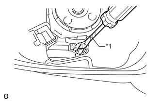
Using a screwdriver, detach the claw.
| *1 | Protective Tape |
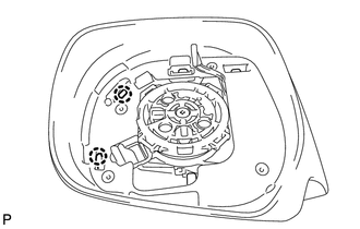
Detach the 2 claws and remove the outer mirror cover.
- NOTICE:
-
When removing the cover, be careful not to damage the side turn signal light assembly or cover.
81740
3.REMOVE SIDE TURN SIGNAL LIGHT ASSEMBLY LH
87966
4.REMOVE OUTER MIRROR RETRACTOR LH
Remove the outer rear view mirror gasket LH.
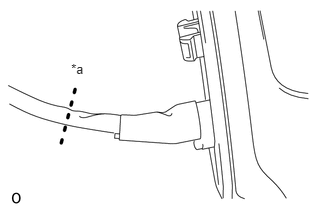
Cut the wire harness sub-assembly at the location shown in the illustration.
- HINT:
-
A new wire harness sub-assembly is used for reassembly.
| *a | Cut here |
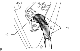
Remove the tape and detach the clamp.
| *1 | Tape |
| *2 | Clamp |
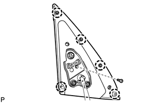
Remove the screw, detach the 5 claws and remove the outer rear view mirror gasket LH.
Remove the lower mirror cover.
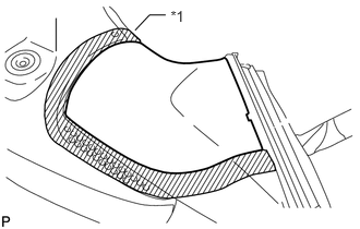
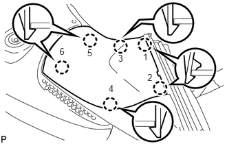
Put protective tape around the lower mirror cover.
| *1 | Protective Tape |
- HINT:
-
The claws of the mirror will be detached in the order shown in the illustration in the following steps.
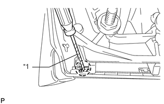
Using a screwdriver, detach the claw.
| *1 | Protective Tape |
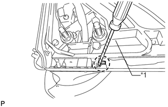
Using a screwdriver, detach the claw.
| *1 | Protective Tape |
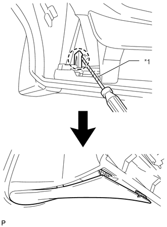
Using a screwdriver, detach the claw to create a space between the lower mirror cover and mirror body as shown in the illustration.
| *1 | Protective Tape |
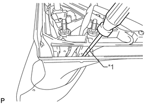
Insert a screwdriver as shown in the illustration.
| *1 | Protective Tape |
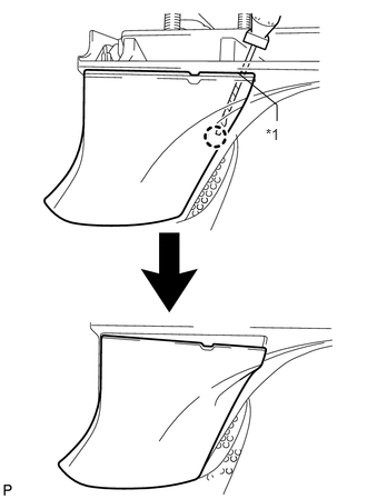
Detach the claw to create a space between the lower mirror cover and cover base as shown in the illustration.
| *1 | Protective Tape |
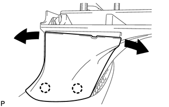
While moving the lower mirror cover back and forth in the directions of the arrows in the illustration, detach the 3 claws and remove the lower mirror cover.
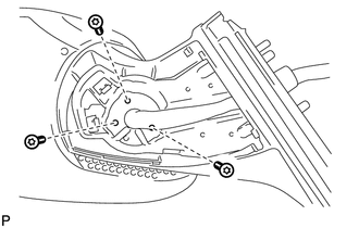
Using a T25 "TORX" socket wrench, remove the 3 screws.
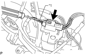
w/ Side Monitor System:
Remove the connector from the wire clip.
Disconnect the connector.
- NOTICE:
-
When disconnecting the connector, be careful not to damage it.
| *1 | Protective Tape |
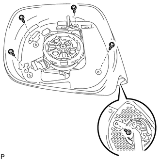
Remove the 5 screws and outer mirror body.
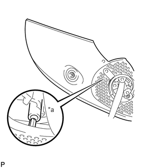
Detach the claw and remove the cover body.
- NOTICE:
-
Be careful as the claw shown in the part of the illustration labeled A is easily damaged.
| *a | A |
Remove the actuator sub-assembly.
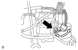
Slide the cover as shown in the illustration and disconnect the connector.
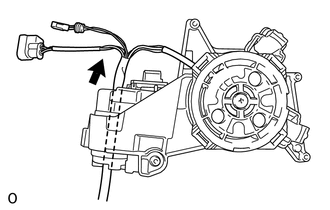
Pull out the wire harness sub-assembly in the direction indicated by the arrow in the illustration.
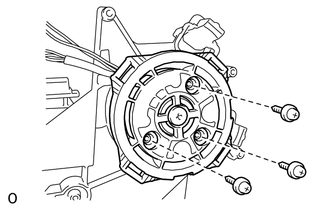
Remove the 3 screws and actuator sub-assembly.
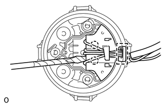
Detach the clamp.
Using a thin-bladed screwdriver with its tip wrapped with protective tape, detach the two claws and disconnect the connector.
w/ Side Monitor System:
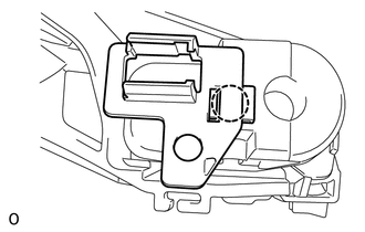
Detach the claw and remove the wire clip.
Remove the support spring.
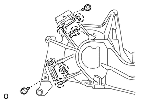
Remove the 2 screws, and then detach the 6 claws and remove the 2 support springs.
86790C
5.REMOVE SIDE TELEVISION CAMERA ASSEMBLY (w/ Side Monitor System)
Remove the side television camera assembly (See page Audio / Visual / Telematics>PARK ASSIST / MONITORING>TELEVISION CAMERA (for Side)>REMOVAL).