Home › Vehicle Interior › HEATING / AIR CONDITIONING › COMBUSTION TYPE POWER HEATER SYSTEM › from 2017.08
RM27T0E _58 Vehicle Interior _053739 HEATING / AIR CONDITIONING _0261205 COMBUSTION TYPE POWER HEATER SYSTEM J

HEATING / AIR CONDITIONING  COMBUSTION TYPE POWER HEATER SYSTEM  Power Heater Switch Circuit  


DESCRIPTION

When the heater switch assembly (power heater switch) is turned on, the heater assembly sends a drive signal to the heater pump assembly. The heater assembly then receives the fuel necessary for combustion and starts operating.

WIRING DIAGRAM
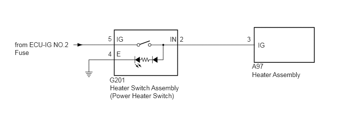
E323850E03
2.323,1.615 2.896,1.781 0.573,0.167 10 false G201 0.313,0.865 1.531,1.167 1.219,0.302 10 false from ECU-IG NO.2 Fuse 2.333,1.781 4.135,2.24 1.802,0.458 10 false Heater Switch Assembly (Power Heater Switch) 5.344,1.323 5.917,1.49 0.573,0.167 10 false A97 5.344,1.5 6.5,1.74 1.156,0.24 10 false Heater Assembly 2.292,0.74 2.417,0.896 0.125,0.156 10 false 5 2.469,0.75 2.771,0.906 0.302,0.156 10 false IG 3.604,0.75 3.906,0.906 0.302,0.156 10 false IN 5.469,0.875 5.771,1.031 0.302,0.156 10 false IG 5.24,0.75 5.542,0.906 0.302,0.156 10 false 3 3.813,0.75 4.115,0.906 0.302,0.156 10 false 2 2.292,1.063 2.417,1.219 0.125,0.156 10 false 4 2.469,1.063 2.771,1.219 0.302,0.156 10 false E

CAUTION / NOTICE / HINT

NOTICE:

Inspect the fuses for circuits related to this system before performing the following inspection procedure.


PROCEDURE
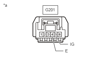
1.CHECK HARNESS AND CONNECTOR (HEATER SWITCH ASSEMBLY - BATTERY AND BODY GROUND)
a.
E381165E01
1.458,0.188 1.969,0.49 0.51,0.302 1.906,1.229 2.052,1.51 2.052,1.51 2.313,1.51 true 1.771,1.229 1.896,1.74 1.896,1.74 2.156,1.74 true 1.542,0.25 2.156,0.448 0.615,0.198 10 false G201 2.385,1.427 3,1.625 0.615,0.198 10 false IG 0.115,0.094 0.729,0.292 0.615,0.198 10 false *a 2.219,1.656 2.833,1.854 0.615,0.198 10 false E

Disconnect the heater switch assembly (power heater switch) connector.


b.

Measure the voltage according to the value(s) in the table below.

Standard Voltage:
Tester Connection Switch Condition Specified Condition
G201-5 (IG) - Body ground Engine switch on (IG) 11 to 14 V
G201-5 (IG) - Body ground Engine switch off Below 1 V


c.

Measure the resistance according to the value(s) in the table below.

Standard Resistance:
Tester Connection Condition Specified Condition
G201-4 (E) - Body ground Always Below 1 Ω


Text in Illustration
*a Front view of wire harness connector
(to Heater Switch Assembly [Power Heater Switch])


OK

2.INSPECT HEATER SWITCH ASSEMBLY (POWER HEATER SWITCH)

NG

REPAIR OR REPLACE HARNESS OR CONNECTOR

2.INSPECT HEATER SWITCH ASSEMBLY (POWER HEATER SWITCH)
a.

Remove the heater switch assembly (power heater switch) (See page Vehicle Interior>HEATING / AIR CONDITIONING>HEATER SWITCH>REMOVAL).


b.

Inspect the heater switch assembly (power heater switch) (See page Vehicle Interior>HEATING / AIR CONDITIONING>HEATER SWITCH>INSPECTION ).


OK

3.CHECK HARNESS AND CONNECTOR (HEATER SWITCH ASSEMBLY - HEATER ASSEMBLY)

NG

REPLACE HEATER SWITCH ASSEMBLY (POWER HEATER SWITCH)

3.CHECK HARNESS AND CONNECTOR (HEATER SWITCH ASSEMBLY - HEATER ASSEMBLY)
a.

Disconnect the G201 heater switch assembly (power heater switch) connector.


b.

Disconnect the A97 heater assembly connector.


c.

Measure the resistance according to the value(s) in the table below.

Standard Resistance:
Tester Connection Switch Condition Specified Condition
G201-2 (IN) - A97-3 (IG) Always Below 1 Ω
A97-3 (IG) - Body ground Always 10 kΩor higher


OK

PROCEED TO NEXT SUSPECTED AREA SHOWN IN PROBLEM SYMPTOMS TABLE

NG

REPAIR OR REPLACE HARNESS OR CONNECTOR