VF4BM TRANSFER / 4WD / AWD TRANSFER SYSTEM P163B 4WD ECU Malfunction
DESCRIPTION
This DTC is output when a malfunction is detected in the 4 wheel drive control ECU internal circuit.
| DTC No. | DTC Detection Condition
1.
Diagnosis Condition 2.
Malfunction Status 3.
Malfunction Time 4.
Other |
Trouble Area |
|---|---|---|
| P163B | 1.
While the ignition switch is turned to ON or directly after the ignition switch is turned to ON 2.
4 wheel drive control ECU internal circuit malfunction 3.
0.5 seconds or more (if directly after the ignition switch is turned to ON, 0.05 seconds or more) 4.
1 trip detection logic |
·
Wire harness and connector ·
Transfer shift actuator assembly ·
Differential lock shift actuator* ·
4 wheel drive control ECU |
*: w/ Rear Differential Lock
WIRING DIAGRAM
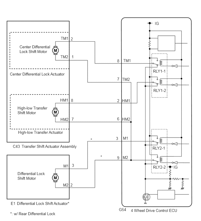
PROCEDURE
Turn the ignition switch off.
Disconnect the G54 4 wheel drive control ECU connector.
Disconnect the C43 transfer shift actuator assembly connector.
Measure the resistance according to the value(s) in the table below.
- Standard Resistance:
Tester Connection Condition Specified Condition G54-8 (TM1) or C43-2 (TM1) - Body ground Always 10 kΩ or higher G54-7 (TM2) or C43-1 (TM2) - Body ground Always 10 kΩ or higher G54-2 (HM1) or C43-8 (HM1) - Body ground Always 10 kΩ or higher G54-6 (HM2) or C43-7 (HM2) - Body ground Always 10 kΩ or higher
OK
NG
Turn the ignition switch off.
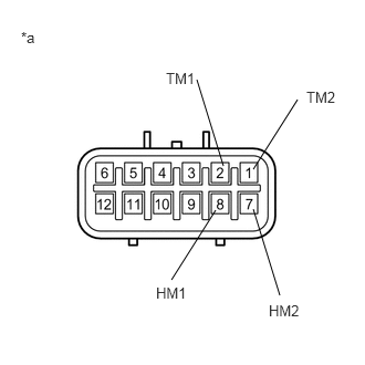
Disconnect the C43 transfer shift actuator assembly connector.
Measure the resistance according to the value(s) in the table below.
- Standard Resistance:
Tester Connection Condition Specified Condition 2 (TM1) - 1 (TM2) Always 1.5 to 100 Ω 2 (TM1) or 1 (TM2) - Body ground Always 10 kΩ or higher 8 (HM1) - 7 (HM2) Always 1.5 to 100 Ω 8 (HM1) or 7 (HM2) - Body ground Always 10 kΩ or higher
| *a | Component without harness connected
(Transfer Shift Actuator Assembly) |
- Result:
Result Proceed to OK (w/ Rear Differential Lock) A OK (w/o Rear Differential Lock) B NG C
A
B
C
Turn the ignition switch off.
Disconnect the G54 4 wheel drive control ECU connector.
Disconnect the E1 differential lock shift actuator connector.
Measure the resistance according to the value(s) in the table below.
- Standard Resistance:
Tester Connection Condition Specified Condition G54-3 (M1) - E1-3 (M1) Always Below 1 Ω G54-9 (M2) - E1-2 (M2) Always Below 1 Ω G54-3 (M1) or E1-3 (M1) - Body ground Always 10 kΩ or higher G54-9 (M2) or E1-2 (M2) - Body ground Always 10 kΩ or higher
Measure the voltage according to the value(s) in the table below.
- Standard Voltage:
Tester Connection Condition Specified Condition G54-3 (M1) or E1-3 (M1) - Body ground Always Below 1 V G54-9 (M2) or E1-2 (M2) - Body ground Always Below 1 V
OK
NG
Turn the ignition switch off.
Disconnect the E1 differential lock shift actuator connector.
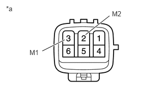
Measure the resistance according to the value(s) in the table below.
- Standard Resistance:
Tester Connection Condition Specified Condition 3 (M1) - 2 (M2) Always 100 Ω or less 3 (M1) or 2 (M2) - Body ground Always 10 kΩ or higher
| *a | Component without harness connected
(Differential Lock Shift Actuator) |
Measure the voltage according to the value(s) in the table below.
- Standard Voltage:
Tester Connection Condition Specified Condition 3 (M1) or 2 (M2) - Body ground Ignition switch ON Below 1 V
OK
NG