Home › Vehicle Interior › LIGHTING (INT) › LIGHTING SYSTEM (except 5L-E) › 2017.08–2020.08
RM27T0E _58 Vehicle Interior _053732 LIGHTING (INT) _0326432 LIGHTING SYSTEM(except 5L-E) J

LIGHTING (INT)  LIGHTING SYSTEM(except 5L-E)  Interior Light Circuit  


DESCRIPTION

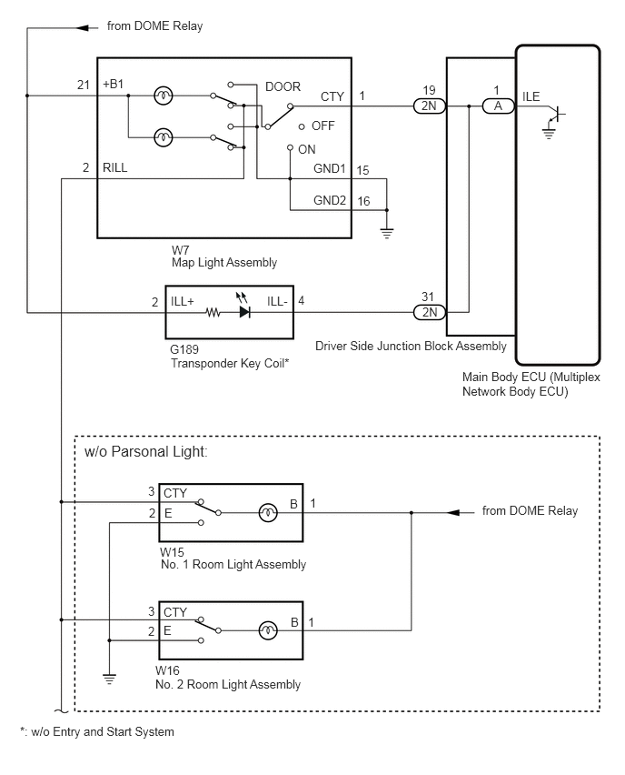
The main body ECU (multiplex network body ECU) controls the operation of the following lights:

·

Map light assembly

·

No. 1 room light assembly

·

No. 2 room light assembly

·

Transponder key coil (w/o Entry and Start System)


WIRING DIAGRAM
E374916E02
1.229,0.208 3.521,0.406 2.292,0.198 10 false from DOME Relay 5.531,5.76 6.729,6.063 1.198,0.302 10 false from DOME Relay 0.969,5.063 3.156,5.406 2.188,0.344 12 false w/o Parsonal Light: 3.615,3.875 6.021,4.073 2.406,0.198 10 false Driver Side Junction Block Assembly 5.302,4.229 6.979,4.646 1.677,0.417 10 false Main Body ECU (Multiplex Network Body ECU) 5.99,1.021 6.385,1.271 0.396,0.25 10 false ILE 5.667,1.125 6.063,1.375 0.396,0.25 10 false A 5.656,0.948 6.052,1.198 0.396,0.25 10 false 1 4.833,1.125 5.229,1.375 0.396,0.25 10 false 2N 4.844,0.948 5.24,1.198 0.396,0.25 10 false 19 4.844,3.49 5.24,3.74 0.396,0.25 10 false 2N 4.833,3.313 5.229,3.563 0.396,0.25 10 false 31 1.969,2.781 4.375,2.979 2.406,0.198 10 false W7 1.969,2.917 4.375,3.115 2.406,0.198 10 false Map Light Assembly 3.677,1.021 4.313,1.229 0.635,0.208 10 false CTY 3.594,1.844 4.229,2.052 0.635,0.208 10 false GND1 3.594,2.208 4.229,2.417 0.635,0.208 10 false GND2 4.094,2.219 4.729,2.427 0.635,0.208 10 false 16 4.083,1.865 4.719,2.073 0.635,0.208 10 false 15 4.115,1.01 4.75,1.219 0.635,0.208 10 false 1 3.042,0.906 3.677,1.115 0.635,0.208 10 false DOOR 3.417,1.625 4.052,1.833 0.635,0.208 10 false ON 3.573,1.354 4.208,1.563 0.635,0.208 10 false OFF 1.177,0.875 3.469,1.073 2.292,0.198 10 false +B1 1.177,1.833 3.469,2.031 2.292,0.198 10 false RILL 0.948,1.833 3.24,2.031 2.292,0.198 10 false 2 0.885,0.885 3.177,1.083 2.292,0.198 10 false 21 3.063,3.365 3.698,3.573 0.635,0.208 10 false ILL- 1.958,3.365 2.594,3.573 0.635,0.208 10 false ILL+ 3.417,3.354 4.052,3.563 0.635,0.208 10 false 4 1.74,3.375 2.375,3.583 0.635,0.208 10 false 2 1.948,3.917 4.354,4.115 2.406,0.198 10 false G189 1.958,4.073 4.365,4.271 2.406,0.198 10 false Transponder Key Coil* 1.875,5.563 2.51,5.771 0.635,0.208 10 false CTY 3.323,5.688 3.958,5.896 0.635,0.208 10 false B 3.333,7.042 3.969,7.25 0.635,0.208 10 false B 3.531,7.042 4.167,7.25 0.635,0.208 10 false 1 3.552,5.677 4.188,5.885 0.635,0.208 10 false 1 1.698,5.542 2.333,5.75 0.635,0.208 10 false 3 1.698,6.917 2.333,7.125 0.635,0.208 10 false 3 1.698,7.146 2.333,7.354 0.635,0.208 10 false 2 1.708,5.792 2.344,6 0.635,0.208 10 false 2 1.885,5.792 2.521,6 0.635,0.208 10 false E 1.875,7.135 2.51,7.344 0.635,0.208 10 false E 1.875,6.927 2.51,7.135 0.635,0.208 10 false CTY 1.833,6.24 3.781,6.635 1.948,0.396 10 false W15 1.844,6.375 3.792,6.771 1.948,0.396 10 false No. 1 Room Light Assembly 1.781,7.594 3.729,7.99 1.948,0.396 10 false W16 1.781,7.75 3.729,8.146 1.948,0.396 10 false No. 2 Room Light Assembly 0.229,8.292 2.594,8.573 2.365,0.281 10 false *: w/o Entry and Start System

E374917E01
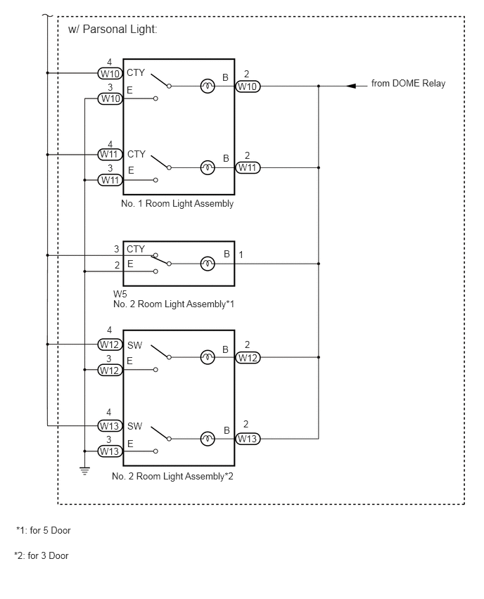
1.01,0.323 4.313,0.563 3.302,0.24 12 false w/ Parsonal Light: 1.792,2.927 5.094,3.167 3.302,0.24 10 false No. 1 Room Light Assembly 5.5,1.146 6.854,1.406 1.354,0.26 10 false from DOME Relay 3.292,1.063 4.646,1.323 1.354,0.26 10 false B 3.302,2.26 4.656,2.521 1.354,0.26 10 false B 1.885,2.198 3.24,2.458 1.354,0.26 10 false CTY 1.875,0.99 3.229,1.25 1.354,0.26 10 false CTY 1.875,1.25 3.229,1.51 1.354,0.26 10 false E 1.896,2.438 3.25,2.698 1.354,0.26 10 false E 3.313,3.677 4.667,3.938 1.354,0.26 10 false B 3.292,5.094 4.646,5.354 1.354,0.26 10 false B 3.313,6.292 4.667,6.552 1.354,0.26 10 false B 1.885,3.823 3.24,4.083 1.354,0.26 10 false E 1.875,5.26 3.229,5.521 1.354,0.26 10 false E 1.885,6.49 3.24,6.75 1.354,0.26 10 false E 1.885,5.031 3.24,5.292 1.354,0.26 10 false SW 1.875,3.604 3.229,3.865 1.354,0.26 10 false CTY 1.885,6.229 3.24,6.49 1.354,0.26 10 false SW 1.479,5.021 2.833,5.281 1.354,0.26 10 false W12 3.531,5.219 4.885,5.479 1.354,0.26 10 false W12 1.479,5.406 2.833,5.667 1.354,0.26 10 false W12 1.479,6.229 2.833,6.49 1.354,0.26 10 false W13 1.479,6.604 2.833,6.865 1.354,0.26 10 false W13 3.521,6.417 4.875,6.677 1.354,0.26 10 false W13 1.677,4.271 4.979,4.51 3.302,0.24 10 false W5 1.677,4.417 4.979,4.656 3.302,0.24 10 false No. 2 Room Light Assembly*1 1.5,2.583 4.802,2.823 3.302,0.24 10 false W11 1.479,2.198 4.781,2.438 3.302,0.24 10 false W11 3.531,2.396 6.833,2.635 3.302,0.24 10 false W11 3.521,1.198 4.427,1.563 0.906,0.365 10 false W10 1.5,1.375 2.406,1.74 0.906,0.365 10 false W10 1.49,1.01 2.396,1.375 0.906,0.365 10 false W10 1.583,0.833 2.49,1.198 0.906,0.365 10 false 4 1.594,2.052 2.5,2.417 0.906,0.365 10 false 4 1.583,4.802 2.49,5.167 0.906,0.365 10 false 4 1.573,6.021 2.479,6.385 0.906,0.365 10 false 4 1.573,6.427 2.479,6.792 0.906,0.365 10 false 3 1.688,3.604 2.594,3.969 0.906,0.365 10 false 3 1.594,2.406 2.5,2.771 0.906,0.365 10 false 3 1.594,1.208 2.5,1.573 0.906,0.365 10 false 3 3.615,1.01 4.521,1.375 0.906,0.365 10 false 2 3.625,2.219 4.531,2.583 0.906,0.365 10 false 2 1.698,3.844 2.604,4.208 0.906,0.365 10 false 2 3.625,5.021 4.531,5.385 0.906,0.365 10 false 2 3.604,6.198 4.51,6.563 0.906,0.365 10 false 2 3.531,3.688 4.438,4.052 0.906,0.365 10 false 1 1.656,6.969 4.958,7.208 3.302,0.24 10 false No. 2 Room Light Assembly*2 0.24,7.771 3.542,8.01 3.302,0.24 10 false *1: for 5 Door 0.208,8.146 3.51,8.385 3.302,0.24 10 false *2: for 3 Door 1.573,5.229 2.479,5.594 0.906,0.365 10 false 3

CAUTION / NOTICE / HINT

NOTICE:

Before replacing the main body ECU (multiplex network body ECU), refer to Service Bulletin.


PROCEDURE

1.PERFORM ACTIVE TEST USING GTS
a.

Perform the Active Test according to the display on the GTS.

Click hereVehicle Interior>LIGHTING (INT)>LIGHTING SYSTEM (except 5L-E)>DATA LIST / ACTIVE TEST

Main Body
Tester Display Measurement Item Control Range Diagnostic Note

*: w/o Entry and Start System

Illuminated Entry System Map light assembly, transponder key coil*, No. 1 room light assembly and No. 2 room light assembly OFF or ON Turn the map light assembly, No. 1 room light assembly and No. 2 room light assembly to the DOOR position.

OK:

All lights illuminates.


Result:
Proceed to
OK
NG


OK

PROCEED TO NEXT SUSPECTED AREA SHOWN IN PROBLEM SYMPTOMS TABLE

NG

2.CHECK DRIVER SIDE JUNCTION BLOCK ASSEMBLY
a.
E377410C01
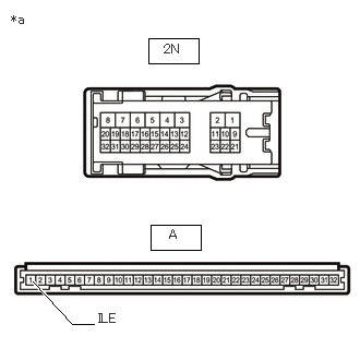
1.438,2.146 1.917,2.385 0.479,0.24 1.417,0.365 1.896,0.604 0.479,0.24 0.313,2.688 0.688,3.094 0.688,3.094 0.896,3.094 true 0.104,0.115 0.417,0.271 0.313,0.156 10 false *a 1.563,0.396 1.875,0.552 0.313,0.156 10 false 2N 1.615,2.167 1.927,2.323 0.313,0.156 10 false A 0.938,2.969 1.375,3.219 0.438,0.25 10 false ILE
*a Component without harness connected
(Driver Side Junction Block Assembly)


Remove the driver side junction block assembly.

Click herePower Source / Network>POWER DISTRIBUTION>MAIN BODY ECU>REMOVAL


b.

Remove the main body ECU (multiplex network body ECU) from the driver side junction block assembly.

Click herePower Source / Network>POWER DISTRIBUTION>MAIN BODY ECU>REMOVAL


c.

Measure the resistance according to the value(s) in the table below.

Standard Resistance:
Tester Connection Condition Specified Condition
2N-19 - A-1 (ILE) Always Below 1 Ω
2N-31 - A-1 (ILE) Always Below 1 Ω


Result:
Proceed to
OK
NG


OK

REPLACE MAIN BODY ECU (MULTIPLEX NETWORK BODY ECU)

NG

REPLACE DRIVER SIDE JUNCTION BLOCK ASSEMBLY