WIPER / WASHER WIPER AND WASHER SYSTEM TERMINALS OF ECU
CHECK WINDSHIELD WIPER RELAY ASSEMBLY (w/ Rain Sensor)
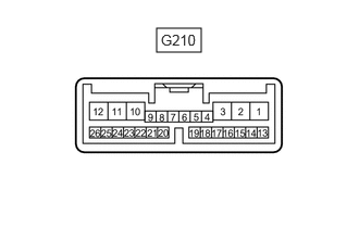
Disconnect the G210 windshield wiper relay assembly connector.
Measure the voltage and resistance according to the value(s) in the table below.
- HINT:
-
Measure the values on the wire harness side with the connector disconnected.
| Terminal No. (Symbol) | Wiring Color | Terminal Description | Condition | Specified Condition |
|---|---|---|---|---|
| G210-2 (IG) - Body ground | G - Body ground | IG power supply | Ignition switch ON | 11 to 14 V |
| Ignition switch off | Below 1 V | |||
| G210-8 (VR2) - G210-21 (VR1) | P - LG | Adjusting volume circuit | Windshield wiper switch assembly adjusting ring changed | 0 to 231 Ω |
| G210-12 (E) - Body ground | W-B - Body ground | Body ground | Always | Below 1 Ω |
| G210-16 (WIG) - Body ground | GR - Body ground | IG power supply | Ignition switch ON | 11 to 14 V |
| Ignition switch off | Below 1 V |
Reconnect the G210 windshield wiper relay assembly connector.
Measure the voltage according to the value(s) in the table below.
| Terminal No. (Symbol) | Wiring Color | Terminal Description | Condition | Specified Condition |
|---|---|---|---|---|
| G210-1 (+SM) - Body ground | W - Body ground | Front wiper motor operation signal | Front wiper motor in low or high operation | 11 to 14 V |
| Front wiper motor not operating | Below 1 V | |||
| G210-3 (C1) - G210-5 (C0) | GR - V | Front wiper switch AUTO position signal | Ignition switch ON, windshield wiper switch assembly in AUTO position | Below 1 V |
| Ignition switch ON, windshield wiper switch assembly in not AUTO position | 11 to 14 V | |||
| G210-10 (+1) - Body ground | W - Body ground | Front wiper motor low speed signal | Ignition switch ON, front wiper motor in low operation | 11 to 14 V |
| Ignition switch ON, front wiper motor not operating | Below 1 V | |||
| G210-11 (+2) - Body ground | R - Body ground | Front wiper motor high speed signal | Ignition switch ON, front wiper motor in high operation | 11 to 14 V |
| Ignition switch ON, front wiper motor not operating | Below 1 V | |||
| G210-25 (W) - Body ground | L - Body ground | Front washer motor signal | Ignition switch ON, front washer switch off | 11 to 14 V |
| Ignition switch ON, front washer switch on | Below 1 V |
Measure the voltage and waveform according to the value(s) in the table below.
| Terminal No. (Symbol) | Wiring Color | Terminal Description | Condition | Specified Condition |
|---|---|---|---|---|
| G210-14 (MPX1) - Body ground | P - Body ground | LIN communication signal | Ignition switch ON | Pulse generation |
| Ignition switch off | Below 1 V | |||
| G210-24 (SPD) - Body ground | R - Body ground | Vehicle speed signal | Driving at approximately 20 km/h (12 mph) | Pulse generation (See waveform 1) |
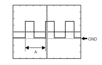
Waveform 1 (Reference):
| Item | Condition |
|---|---|
| Tester Connection | G210-24 (SPD) - Body ground |
| Tool Setting | 5 V/DIV., 20 ms./DIV. |
| Vehicle Condition | Driving at approximately 20 km/h (12 mph) |
- HINT:
-
When the system is functioning normally, one wheel revolution generates 4 pulses. As the vehicle speed increases, the width indicated by A in the illustration narrows.
CHECK HEADLIGHT CLEANER CONTROL RELAY (w/ Headlight Cleaner System)
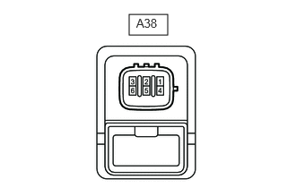
Disconnect the A38 headlight cleaner control relay connector.
Measure the voltage and resistance according to the value(s) in the table below.
| Terminal No. (Symbol) | Wiring Color | Terminal Description | Condition | Specified Condition |
|---|---|---|---|---|
| A38-1 (HDLO) - A38-4 (E) | V - W-B | Low beam headlight signal | Headlight dimmer switch in head | 11 to 14 V |
| A38-1 (HDLO) - A38-4 (E) | V - W-B | Low beam headlight signal | Headlight dimmer switch not in head | Below 1 V |
| A38-3 (IG) - A38-4 (E) | L - W-B | Ignition switch power supply | Ignition switch ON | 11 to 14 V |
| A38-3 (IG) - A38-4 (E) | L - W-B | Ignition switch power supply | Ignition switch off | Below 1 V |
| A38-4 (E) - Body ground | W-B - Body ground | Body ground | Always | Below 1 Ω |
| A38-5 (FRWA) - A38-4 (E) | B - W-B | Front washer switch operation signal | Front washer motor switch on | Below 1 V |
| A38-5 (FRWA) - A38-4 (E) | B - W-B | Front washer switch operation signal | Front washer motor switch off | 11 to 14 V |
NO. 1 HEADLIGHT ECU SUB-ASSEMBLY RH (w/ Headlight Cleaner System, LED Headlight)
Disconnect the A103 No. 1 headlight light ECU sub-assembly RH connector.
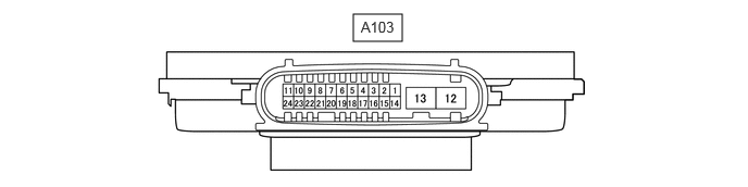
Measure the resistance and voltage according to the value(s) in the table below.
- HINT:
-
Measure the values on the wire harness side with the connector disconnected.
| Terminal No. (Symbol) | Wiring Color | Terminal Description | Condition | Specified Condition |
|---|---|---|---|---|
| A103-4 (IG) - Body ground | GR - Body ground | IG power supply | Ignition switch off | Below 1 V |
| Ignition switch ON | 11 to 14 V | |||
| A103-12 (GND) - Body ground | W-B - Body ground | Body ground | Always | Below 1 Ω |
Reconnect the A103 No. 1 headlight light ECU sub-assembly RH connector.
Measure the voltage according to the value(s) in the table below.
| Terminal No. (Symbol) | Wiring Color | Terminal Description | Condition | Specified Condition |
|---|---|---|---|---|
| A103-7 (HLC) - Body ground | V - Body ground | Headlight cleaner motor operation signal | Headlight cleaner motor not operating | 11 to 14 V |
| Headlight cleaner motor operating | Below 1 V |
CHECK COMBINATION METER ASSEMBLY (w/ Rain Sensor)
Disconnect the G304 combination meter assembly connector.
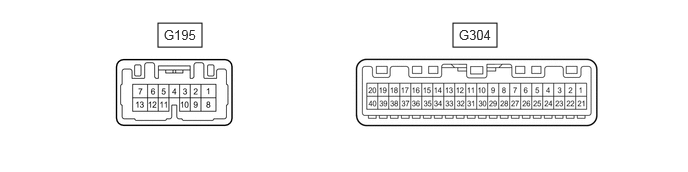
Measure the voltage and resistance according to the value(s) in the table below.
- HINT:
-
Measure the values on the wire harness side with the connector disconnected.
| Terminal No. (Symbol) | Wiring Color | Terminal Description | Condition | Specified Condition |
|---|---|---|---|---|
| G304-21 (B) - Body ground | L - Body ground | Battery power supply | Always | 11 to 14 V |
| G304-22 (IG+) - Body ground | R - Body ground | IG power supply | Ignition switch ON | 11 to 14 V |
| Ignition switch off | Below 1 V | |||
| G304-20 (E2) - Body ground | BR - Body ground | Body ground | Always | Below 1 Ω |
Reconnect the G304 combination meter assembly connector.
Measure the voltage according to the value(s) in the table below.
| Terminal No. (Symbol) | Wiring Color | Terminal Description | Condition | Specified Condition |
|---|---|---|---|---|
|
*: w/ Washer Level Warning System |
||||
| G304-30 (WLVL)* - Body ground | W - Body ground | Washer fluid level signal | Ignition switch ON, washer fluid level not low | 11 to 14 V |
| Ignition switch ON, washer fluid level low | Below 1 V | |||
Measure the waveform according to the value(s) in the table below.
| Terminal No. (Symbol) | Wiring Color | Terminal Description | Condition | Specified Condition |
|---|---|---|---|---|
| G304-17 (+S) - Body ground | R - Body ground | Speed signal for other system (Output) | Driving at approximately 20 km/h (12 mph) | Pulse generation (See waveform 1) |
Waveform 1 (Reference):
| Item | Condition |
|---|---|
| Tester Connection | G304-17 (+S) - Body ground |
| Tool Setting | 5 V/DIV., 20 ms./DIV. |
| Vehicle Condition | Driving at approximately 20 km/h (12 mph) |
- HINT:
-
When the system is functioning normally, one wheel revolution generates 4 pulses. As the vehicle speed increases, the width indicated by A in the illustration narrows.
CHECK DRIVER SIDE JUNCTION BLOCK ASSEMBLY, MAIN BODY ECU (MULTIPLEX NETWORK BODY ECU) (for 5L-E)
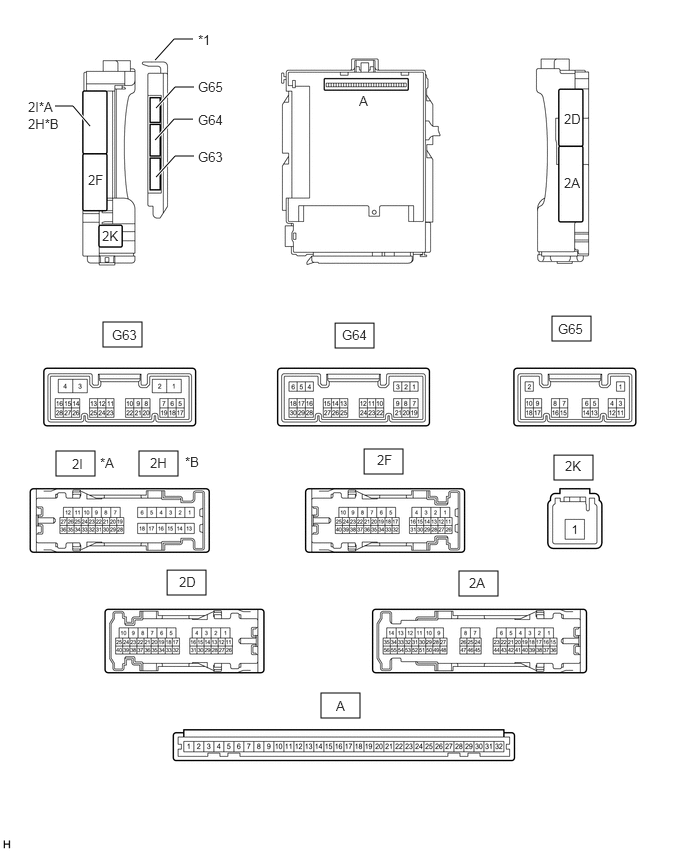
| *A | for LHD | *B | for RHD |
| *1 | Main Body ECU (Multiplex Network Body ECU) | - | - |
Remove the main body ECU (multiplex network body ECU) from the driver side junction block assembly.
Click herePower Source / Network>POWER DISTRIBUTION>MAIN BODY ECU>REMOVAL
Connect the driver side junction block assembly connector.
Measure the voltage and resistance according to the value(s) in the table below.
| Terminal No. (Symbol) | Wiring Color | Terminal Description | Condition | Specified Condition |
|---|---|---|---|---|
| A-32 (IG) - Body ground | None - Body ground | IG power supply | Ignition switch ON | 11 to 14 V |
| Ignition switch off | Below 1 V | |||
| A-31 (BECU) - Body ground | None - Body ground | Battery power supply | Always | 11 to 14 V |
| A-30 (ACC) - Body ground | None - Body ground | ACC power supply | Ignition switch ACC | 11 to 14 V |
| Ignition switch off | Below 1 V | |||
| A-11 (GND1) - Body ground | None - Body ground | Body ground | Always | Below 1 Ω |
| G63-3 (GND2) - Body ground | W-B - Body ground | Body ground | Always | Below 1 Ω |
Install the main body ECU (multiplex network body ECU).
Click herePower Source / Network>POWER DISTRIBUTION>MAIN BODY ECU>INSTALLATION
Measure the voltage and check for pulses according to the value(s) in the table below.
| Terminal No. (Symbol) | Wiring Color | Terminal Description | Condition | Specified Condition |
|---|---|---|---|---|
| G63-16 (HDLO) - G63-3 (GND2) | V - W-B | Low beam headlight signal | Headlight dimmer switch in head | 11 to 14 V |
| Headlight dimmer switch not in head | Below 1 V | |||
| G63-20 (RWMR) - G63-3 (GND2) | B - W-B | Rear wiper power supply input | Ignition switch ON, glass hatch open | Below 1 V |
| Ignition switch ON, glass hatch closed | 11 to 14 V | |||
| G64-1 (GCTY) - 2D-4 (GND1) | V - W-B | Glass hatch courtesy light switch signal | Glass hatch open | Below 1 V |
| Glass hatch closed | Pulse generation
(See waveform 1 or 2) |
|||
| G64-6 (RCTY) - 2D-4 (GND1) | R - W-B | Rear door courtesy light switch RH signal | Rear door RH open | Below 1 V |
| Rear door RH closed | 11 to 14 V | |||
| G64-19 (BCTY) - 2D-4 (GND1) | G - W-B | Back door courtesy light switch signal | Back door open | Below 1 V |
| Back door closed | Pulse generation
(See waveform 3 or 4) |
|||
| G65-3 (LCTY) - 2D-4 (GND1) | V - W-B | Rear door courtesy light switch LH signal | Rear door LH open | Below 1 V |
| Rear door LH closed | 11 to 14 V |
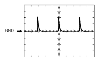
Waveform 1
| Item | Content |
|---|---|
| Terminal No. (Symbol) | G64-1 (GCTY) - 2D-4 (GND1) |
| Tool setting | 5 V/DIV., 20 ms./DIV. |
| Condition | Glass hatch closed |
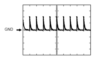
Waveform 2
| Item | Content |
|---|---|
| Terminal No. (Symbol) | G64-1 (GCTY) - 2D-4 (GND1) |
| Tool setting | 5 V/DIV., 20 ms./DIV. |
| Condition | Glass hatch closed |
Waveform 3
| Item | Content |
|---|---|
| Terminal No. (Symbol) | G64-19 (BCTY) - 2D-4 (GND1) |
| Tool setting | 5 V/DIV., 20 ms./DIV. |
| Condition | Back door closed |
Waveform 4
| Item | Content |
|---|---|
| Terminal No. (Symbol) | G64-19 (BCTY) - 2D-4 (GND1) |
| Tool setting | 5 V/DIV., 20 ms./DIV. |
| Condition | Back door closed |
CHECK DRIVER SIDE JUNCTION BLOCK ASSEMBLY, MAIN BODY ECU (MULTIPLEX NETWORK BODY ECU) (except 5L-E)
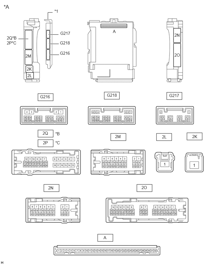
| *A | Main Body ECU (Multiplex Network Body ECU) with 3 connectors | *B | for LHD |
| *C | for RHD | - | - |
| *1 | Main Body ECU (Multiplex Network Body ECU) | - | - |
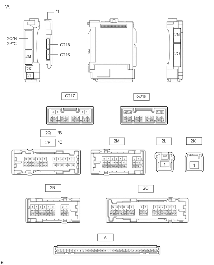
| *A | Main Body ECU (Multiplex Network Body ECU) with 2 connectors | *B | for LHD |
| *C | for RHD | - | - |
| *1 | Main Body ECU (Multiplex Network Body ECU) | - | - |
Remove the main body ECU (multiplex network body ECU) from the driver side junction block assembly.
Click herePower Source / Network>POWER DISTRIBUTION>MAIN BODY ECU>REMOVAL
Connect the driver side junction block assembly connector.
Measure the voltage and resistance according to the value(s) in the table below.
| Terminal No. (Symbol) | Wiring Color | Terminal Description | Condition | Specified Condition |
|---|---|---|---|---|
| A-32 (IG) - Body ground | None - Body ground | IG power supply | Ignition switch ON | 11 to 14 V |
| Ignition switch off | Below 1 V | |||
| A-31 (BECU) - Body ground | None - Body ground | Battery power supply | Always | 11 to 14 V |
| A-30 (ACC) - Body ground | None - Body ground | ACC power supply | Ignition switch ACC | 11 to 14 V |
| Ignition switch off | Below 1 V | |||
| A-11 (GND1) - Body ground | None - Body ground | Body ground | Always | Below 1 Ω |
Install the main body ECU (multiplex network body ECU).
Click herePower Source / Network>POWER DISTRIBUTION>MAIN BODY ECU>INSTALLATION
Measure the voltage according to the value(s) in the table below.
| Terminal No. (Symbol) | Wiring Color | Terminal Description | Condition | Specified Condition |
|---|---|---|---|---|
|
*1: w/ Washer Nozzle Heater System *2: for LHD *3: for RHD *4: for 5 Door *5: w/ Glass Hatch Opener System |
||||
| G216-19 (RWMR) - Body ground | P - Body ground | Rear wiper power supply input | Ignition switch ON, glass hatch open | Below 1 V |
| Ignition switch ON, glass hatch closed | 11 to 14 V | |||
| G216-20 (WHTR) - Body ground*1 | GR - Body ground | Washer nozzle heater signal circuit | Ignition switch ON, ambient temperature 5°C (41°F) or less | Below 1 V |
| Ignition switch ON, ambient temperature 6°C (42°F) or higher | 11 to 14 V | |||
| G216-27 (GCTY) - Body ground*5 | V - Body ground | Glass hatch courtesy light switch signal | Glass hatch open | Below 1 V |
| Glass hatch closed | 8 to 12 V | |||
| 2N-30 (RCTY) - Body ground*2, *4
2P-23 (RCTY) - Body ground*3, *4 |
R - Body ground | Rear door courtesy light switch RH signal | Rear door RH open | Below 1 V |
| Rear door RH closed | 11 to 14 V | |||
| 2Q-27 (BCTY) - Body ground*2, *4
2N-27 (BCTY) - Body ground*3, *4 |
G - Body ground | Back door courtesy light switch signal | Back door open | Below 1 V |
| Back door closed | 11 to 14 V | |||
| 2Q-33 (LCTY) - Body ground*2, *4
2O-15 (LCTY) - Body ground*3, *4 |
V - Body ground | Rear door courtesy light switch LH signal | Rear door LH open | Below 1 V |
| Rear door LH closed | 11 to 14 V | |||