Home › Vehicle Interior › DOOR LOCK › KEY REMINDER WARNING SYSTEM › from 2017.08
RM27T0E _58 Vehicle Interior _053730 DOOR LOCK _0261037 KEY REMINDER WARNING SYSTEM U

DOOR LOCK  KEY REMINDER WARNING SYSTEM  TERMINALS OF ECU  


CHECK DRIVER SIDE JUNCTION BLOCK ASSEMBLY AND MAIN BODY ECU (MULTIPLEX NETWORK BODY ECU) (for 5L-E)
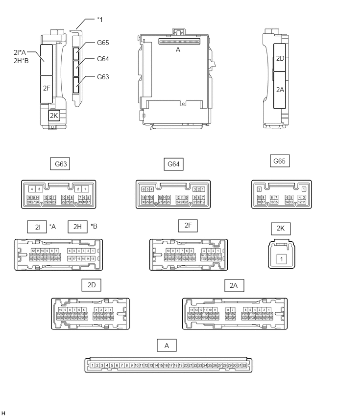

E373866C01
1.073,3.354 1.479,3.615 0.406,0.26 3.49,3.365 3.896,3.625 0.406,0.26 5.75,3.292 6.156,3.552 0.406,0.26 0.583,4.698 0.99,4.958 0.406,0.26 1.448,4.698 1.854,4.958 0.406,0.26 3.792,4.677 4.198,4.938 0.406,0.26 5.771,4.74 6.177,5 0.406,0.26 4.781,5.948 5.188,6.208 0.406,0.26 1.74,5.938 2.146,6.198 0.406,0.26 3.344,7.219 3.75,7.479 0.406,0.26 1.615,0.625 1.813,0.406 1.813,0.406 2.01,0.406 false 1.625,1.125 1.823,0.906 1.823,0.906 2.021,0.906 true 1.615,1.458 1.813,1.24 1.813,1.24 2.01,1.24 true 1.625,1.844 1.823,1.625 1.823,1.625 2.021,1.625 true 0.938,1.313 0.76,1.104 0.76,1.104 0.573,1.104 true 2.063,0.333 2.375,0.531 0.313,0.198 10 false *1 3.74,0.969 3.896,1.167 0.156,0.198 10 false A 5.875,1.156 6.188,1.354 0.313,0.198 10 false 2D 5.875,1.823 6.188,2.021 0.313,0.198 10 false 2A 2.063,1.552 2.521,1.75 0.458,0.198 10 false G63 2.063,1.167 2.521,1.365 0.458,0.198 10 false G64 2.063,0.823 2.521,1.021 0.458,0.198 10 false G65 1.167,3.406 1.625,3.604 0.458,0.198 10 false G63 3.563,3.406 4.021,3.604 0.458,0.198 10 false G64 5.813,3.344 6.271,3.542 0.458,0.198 10 false G65 1.063,2.375 1.375,2.573 0.313,0.198 10 false 2K 0.917,1.792 1.229,1.99 0.313,0.198 10 false 2F 0.292,1.031 0.646,1.25 0.354,0.219 10 false 2I*A 0.292,1.208 0.646,1.427 0.354,0.219 10 false 2H*B 3.5,7.271 3.656,7.469 0.156,0.198 10 false A 4.885,5.99 5.198,6.188 0.313,0.198 10 false 2A 5.885,4.771 6.198,4.969 0.313,0.198 10 false 2K 3.927,4.708 4.24,4.906 0.313,0.198 10 false 2F 1.865,5.979 2.177,6.177 0.313,0.198 10 false 2D 0.75,4.75 1.063,4.948 0.313,0.198 10 false 2I 1.563,4.74 1.875,4.938 0.313,0.198 10 false 2H 1.042,4.74 1.354,4.938 0.313,0.198 10 false *A 1.927,4.729 2.24,4.927 0.313,0.198 10 false *B
*A for LHD *B for RHD
*1 Main Body ECU (Multiplex Network Body ECU) - -


a.

Remove the main body ECU (multiplex network body ECU) from the driver side junction block assembly.

Click herePower Source / Network>POWER DISTRIBUTION>MAIN BODY ECU>REMOVAL


b.

Connect the driver side junction block assembly connectors.


c.

Measure the voltage and resistance according to the value(s) in the table below.

Terminal No. (Symbol) Wiring Color Terminal Description Condition Specified Condition
A-30 (BECU) - Body ground - Battery power supply Always 11 to 14 V
A-31 (ALTB) - Body ground - Battery power supply Always 11 to 14 V
A-32 (IG) - Body ground - Ignition switch power supply Ignition switch ON 11 to 14 V
Ignition switch off Below 1 V
A-29 (ACC) - Body ground - ACC power supply Ignition switch ACC 11 to 14 V
Ignition switch off Below 1 V
A-11 (GND1) - Body ground - Ground Always Below 1 Ω
G64-17 (KSW) - Body ground G - Body ground Unlock warning switch No key in ignition key cylinder 10 kΩ or higher
Key inserted in ignition key cylinder Below 1 Ω


d.

Install the main body ECU (multiplex network body ECU).

Click herePower Source / Network>POWER DISTRIBUTION>MAIN BODY ECU>INSTALLATION


e.

Measure the voltage according to the value(s) in the table below.

Terminal No. (Symbol) Wiring Color Terminal Description Condition Specified Condition
2I-27 (FLCY) - Body ground*1 R - Body ground Front door LH courtesy switch input Front door LH open Below 1 V
Front door LH closed 11 to 14 V
2H-26 (FRCY) - Body ground*2 B - Body ground Front door RH courtesy switch input Front door RH open Below 1 V
Front door RH closed 11 to 14 V

*1: for LHD

*2: for RHD


CHECK DRIVER SIDE JUNCTION BLOCK ASSEMBLY AND MAIN BODY ECU (MULTIPLEX NETWORK BODY ECU) (except 5L-E)
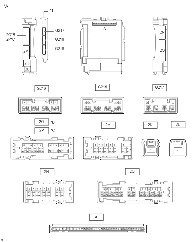

E373864C01
3.271,7.844 3.781,8.083 0.51,0.24 4.583,6.177 5.094,6.417 0.51,0.24 1.469,6.177 1.979,6.417 0.51,0.24 1.271,4.677 1.781,4.917 0.51,0.24 3.708,4.469 4.219,4.708 0.51,0.24 5.24,4.469 5.75,4.708 0.51,0.24 6.26,4.448 6.771,4.688 0.51,0.24 5.583,3.094 6.094,3.333 0.51,0.24 3.49,3.083 4,3.323 0.51,0.24 1.271,3.135 1.781,3.375 0.51,0.24 1.271,4.354 1.781,4.594 0.51,0.24 1.604,0.646 1.604,0.417 1.604,0.417 1.76,0.417 false 0.615,1.302 0.948,1.302 true 1.625,1.156 1.958,1.156 true 1.635,1.469 1.969,1.469 true 1.646,1.833 1.979,1.833 true 1.823,0.292 2.135,0.49 0.313,0.198 10 false *1 0.125,0.125 0.51,0.385 0.385,0.26 12 false *A 0.229,1.188 0.615,1.563 0.385,0.375 10 false 2Q*B 2P*C 0.854,1.792 1.24,2.167 0.385,0.375 10 false 2M 0.896,2.229 1.281,2.604 0.385,0.375 10 false 2K 0.917,2.448 1.302,2.823 0.385,0.375 10 false 2L 3.781,0.969 4.167,1.344 0.385,0.375 10 false A 5.844,1.094 6.229,1.469 0.385,0.375 10 false 2N 5.844,1.76 6.229,2.135 0.385,0.375 10 false 2O 3.469,7.875 3.854,8.25 0.385,0.375 10 false A 6.427,4.479 6.813,4.854 0.385,0.375 10 false 2L 5.406,4.49 5.792,4.865 0.385,0.375 10 false 2K 3.854,4.49 4.24,4.865 0.385,0.375 10 false 2M 1.427,4.375 1.813,4.75 0.385,0.375 10 false 2Q 1.438,4.698 1.823,5.073 0.385,0.375 10 false 2P 1.854,4.698 2.24,5.073 0.385,0.375 10 false *C 1.854,4.396 2.24,4.771 0.385,0.375 10 false *B 1.615,6.208 2,6.583 0.385,0.375 10 false 2N 4.74,6.198 5.125,6.573 0.385,0.375 10 false 2O 2.01,1.698 2.552,2 0.542,0.302 10 false G216 1.344,3.156 1.885,3.458 0.542,0.302 10 false G216 2.021,1.031 2.563,1.333 0.542,0.302 10 false G217 5.667,3.115 6.208,3.417 0.542,0.302 10 false G217 3.583,3.104 4.125,3.406 0.542,0.302 10 false G218 2.01,1.354 2.552,1.656 0.542,0.302 10 false G218
*A Main Body ECU (Multiplex Network Body ECU) with 3 connectors *B for LHD
*C for RHD - -
*1 Main Body ECU (Multiplex Network Body ECU) - -


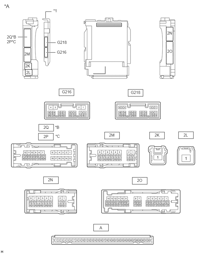
E373865C01
2.063,3.104 2.583,3.344 0.521,0.24 4.479,3.125 5,3.365 0.521,0.24 5.229,4.615 5.75,4.854 0.521,0.24 6.24,4.604 6.76,4.844 0.521,0.24 3.656,4.615 4.177,4.854 0.521,0.24 1.344,4.656 1.865,4.896 0.521,0.24 1.521,6.177 2.042,6.417 0.521,0.24 4.625,6.198 5.146,6.438 0.521,0.24 3.271,7.833 3.792,8.073 0.521,0.24 1.354,4.344 1.875,4.583 0.521,0.24 1.615,1.833 1.938,1.833 true 1.625,1.49 1.948,1.49 true 0.625,1.292 0.948,1.292 true 1.594,0.635 1.594,0.406 1.594,0.406 1.802,0.406 false 0.146,0.115 0.458,0.313 0.313,0.198 12 false *A 0.24,1.208 0.604,1.646 0.365,0.438 10 false 2Q*B 2P*C 2,1.396 2.438,1.844 0.438,0.448 10 false G218 1.99,1.74 2.448,2.208 0.458,0.469 10 false G216 3.479,7.875 3.635,8.073 0.156,0.198 10 false A 4.573,3.146 4.938,3.583 0.365,0.438 10 false G218 2.167,3.125 2.531,3.563 0.365,0.438 10 false G216 1.865,0.292 2.177,0.49 0.313,0.198 10 false *1 0.854,1.802 1.219,2.24 0.365,0.438 10 false 2M 3.813,4.635 4.177,5.073 0.365,0.438 10 false 2M 5.406,4.635 5.771,5.073 0.365,0.438 10 false 2K 0.885,2.219 1.25,2.656 0.365,0.438 10 false 2K 0.917,2.448 1.281,2.885 0.365,0.438 10 false 2L 6.417,4.635 6.781,5.073 0.365,0.438 10 false 2L 1.521,4.365 1.885,4.802 0.365,0.438 10 false 2Q 1.927,4.365 2.292,4.802 0.365,0.438 10 false *B 1.521,4.688 1.885,5.125 0.365,0.438 10 false 2P 1.938,4.677 2.302,5.115 0.365,0.438 10 false *C 5.844,1.073 6.281,1.521 0.438,0.448 10 false 2N 1.677,6.198 2.115,6.646 0.438,0.448 10 false 2N 5.844,1.708 6.281,2.156 0.438,0.448 10 false 2O 4.792,6.219 5.229,6.667 0.438,0.448 10 false 2O
*A Main Body ECU (Multiplex Network Body ECU) with 2 connectors *B for LHD
*C for RHD - -
*1 Main Body ECU (Multiplex Network Body ECU) - -


a.

Remove the main body ECU (multiplex network body ECU) from the driver side junction block assembly.

Click herePower Source / Network>POWER DISTRIBUTION>MAIN BODY ECU>REMOVAL


b.

Connect the driver side junction block assembly connector.


c.

Measure the voltage and resistance according to the value(s) in the table below.

Terminal No. (Symbol) Wiring Color Terminal Description Condition Specified Condition
A-32 (IG) - Body ground - Ignition power supply Ignition switch ON 11 to 14 V
Ignition switch off Below 1 V
A-31 (BECU) - Body ground - Battery power supply Always 11 to 14 V
A-30 (ACC) - Body ground - ACC power supply Ignition switch ACC 11 to 14 V
Ignition switch off Below 1 V
A-11 (GND1) - Body ground - Ground Always Below 1 Ω
A-3 (KSW) - Body ground - Unlock warning switch No key in ignition key cylinder 10 kΩ or higher
Key inserted in ignition key cylinder Below 1 Ω


d.

Install the main body ECU (multiplex network body ECU).

Click herePower Source / Network>POWER DISTRIBUTION>MAIN BODY ECU>INSTALLATION


e.

Measure the voltage according to the value(s) in the table below.

Terminal No. (Symbol) Wiring Color Terminal Description Condition Specified Condition
G218-6 (FLCY) - Body ground*1 R - Body ground Front door courtesy light switch assembly LH signal Front door LH open Below 1 V
Front door LH closed 11 to 14 V
G218-27 (FRCY) - Body ground*2 B - Body ground Front door courtesy light switch assembly RH signal Front door RH open Below 1 V
Front door RH closed 11 to 14 V

*1: for LHD

*2: for RHD