HEATING / AIR CONDITIONING AIR CONDITIONING SYSTEM(for Manual Air Conditioning System) Idle Up Switch Circuit
DESCRIPTION
When the idle up switch is pushed, the air conditioning amplifier assembly outputs the engine idle up signal. If engine idle up does not occur when the idle up switch is pushed, there may be a problem in the circuit shown below.
WIRING DIAGRAM
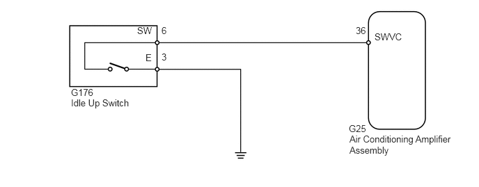
PROCEDURE
Use the Data List to check if the idle up switch is functioning properly (See page Vehicle Interior>HEATING / AIR CONDITIONING>AIR CONDITIONING SYSTEM (for Manual Air Conditioning System)>DATA LIST / ACTIVE TEST).
| Tester Display | Measurement Item/Range | Normal Condition | Diagnostic Note |
|---|---|---|---|
| IDLE UP/PWR HEAT Switch | Idle up switch / ON or OFF | ON: Idle up switch on
OFF: Idle up switch off |
- |
- OK:
The display is as specified in the normal condition column.
OK
NG
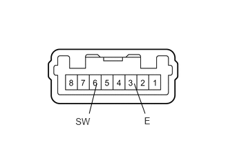
Remove the idle up switch (See page Vehicle Interior>HEATING / AIR CONDITIONING>HEATER SWITCH>REMOVAL).
Measure the resistance according to the value(s) in the table below.
- Standard Resistance:
Tester Connection Switch Condition Specified Condition 6 (SW) - 3 (E) Idle up switch on Below 1 Ω 6 (SW) - 3 (E) Idle up switch off 10 kΩ or higher
OK
NG
Disconnect the G176 switch connector.
Disconnect the G25 amplifier connector.
Measure the resistance according to the value(s) in the table below.
- Standard Resistance:
Tester Connection Condition Specified Condition G176-6 (SW) - G25-36 (SWVC) Always Below 1 Ω G176-3 (E) - Body ground Always Below 1 Ω G25-36 (SWVC) - Body ground Always 10 kΩ or higher
OK
NG