Home › Vehicle Interior › THEFT DETERRENT / KEYLESS ENTRY › THEFT DETERRENT SYSTEM (for 5L-E) › from 2017.08
RM27T0E _58 Vehicle Interior _053731 THEFT DETERRENT / KEYLESS ENTRY _0329512 THEFT DETERRENT SYSTEM(for 5L-E) J

THEFT DETERRENT / KEYLESS ENTRY  THEFT DETERRENT SYSTEM(for 5L-E)  Security Indicator Light Circuit  


DESCRIPTION

When the theft deterrent system is in the disarmed state, the security indicator light will blink if the immobiliser system is set, or not illuminate if the immobiliser system is not set.

When the theft deterrent system is in the armed state, the security indicator light blinks.

When the theft deterrent system is in the arming preparation state or alarm sounding state, the security indicator light illuminates.

WIRING DIAGRAM
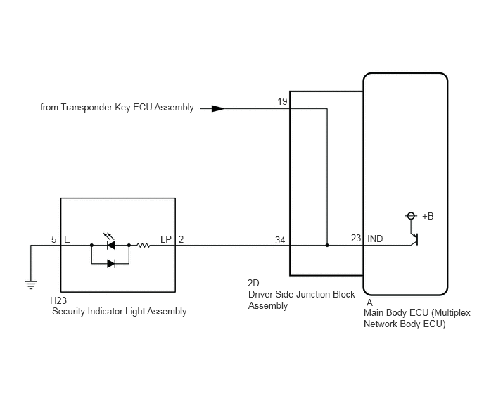
B490781E01
5.385,4.542 7.01,4.896 1.625,0.354 10 false Main Body ECU (Multiplex Network Body ECU) 3.677,4.271 5.302,4.625 1.625,0.354 10 false Driver Side Junction Block Assembly 5.438,3.448 6.156,3.667 0.719,0.219 10 false IND 3.667,4.104 4.385,4.323 0.719,0.219 10 false 2D 5.427,4.396 6.146,4.615 0.719,0.219 10 false A 4.073,3.469 4.792,3.688 0.719,0.219 10 false 34 4.104,1.417 4.823,1.635 0.719,0.219 10 false 19 5.198,3.438 5.917,3.656 0.719,0.219 10 false 23 0.594,1.5 3.24,1.802 2.646,0.302 10 false from Transponder Key ECU Assembly 0.771,4.521 3.417,4.823 2.646,0.302 10 false Security Indicator Light Assembly 0.74,4.365 3.385,4.667 2.646,0.302 10 false H23 2.375,3.458 3.094,3.677 0.719,0.219 10 false LP 0.948,3.458 1.667,3.677 0.719,0.219 10 false E 2.646,3.458 3.365,3.677 0.719,0.219 10 false 2 0.76,3.458 1.479,3.677 0.719,0.219 10 false 5 6.25,3.115 6.969,3.333 0.719,0.219 10 false +B

CAUTION / NOTICE / HINT

NOTICE:

Before performing the inspection, check "Security Indicator Light Does not Blink" in ENGINE IMMOBILISER SYSTEM.

Click hereVehicle Interior>THEFT DETERRENT / KEYLESS ENTRY>ENGINE IMMOBILISER SYSTEM(w/o Entry and Start System)>Security Indicator Light Does not Blink


PROCEDURE

1.PERFORM ACTIVE TEST USING GTS (Security Indicator)
a.

Connect the GTS to the DLC3.


b.

Turn the ignition switch to ON.


c.

Turn the GTS on.


d.

Enter the following menus: Body Electrical / Main Body / Active Test.


e.

According to the display on the GTS, perform the Active Test.

Body Electrical > Main Body > Data List
Tester Display Measurement Item Control Range Diagnostic Note
Security Indicator Security indicator ON or OFF The test is possible when the following conditions are met:
·

The key is in the ignition key cylinder


OK:

Security indicator illuminates when operated through the GTS.


Result:
Proceed to
OK
NG


OK

PROCEED TO NEXT SUSPECTED AREA SHOWN IN PROBLEM SYMPTOMS TABLE

NG

2.INSPECT DRIVER SIDE JUNCTION BLOCK ASSEMBLY
a.

Remove the driver side junction block assembly.

Click herePower Source / Network>POWER DISTRIBUTION>MAIN BODY ECU>REMOVAL


b.

Measure the resistance according to the value(s) in the table below.
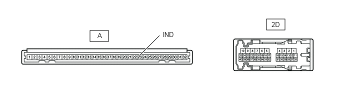
B490785E01
1.875,0.635 2.26,0.865 0.385,0.229 5.552,0.396 5.938,0.625 0.385,0.229 2.906,1.156 3.323,0.74 true 2.031,0.656 2.188,0.854 0.156,0.198 10 false A 5.656,0.427 6.125,0.698 0.469,0.271 10 false 2D 3.385,0.635 3.854,0.906 0.469,0.271 10 false IND

Standard Resistance:
Tester Connection Condition Specified Condition
2D-34 - A-23 (IND) Always Below 1 Ω


Result:
Proceed to
OK
NG


OK

REPLACE MAIN BODY ECU (MULTIPLEX NETWORK BODY ECU)

NG

REPAIR OR REPLACE HARNESS OR CONNECTOR