TIRE PRESSURE MONITORING TIRE PRESSURE WARNING SYSTEM ECU Power Source Circuit
DESCRIPTION
The IG circuit is the power source for the tire pressure warning ECU and receiver.
WIRING DIAGRAM
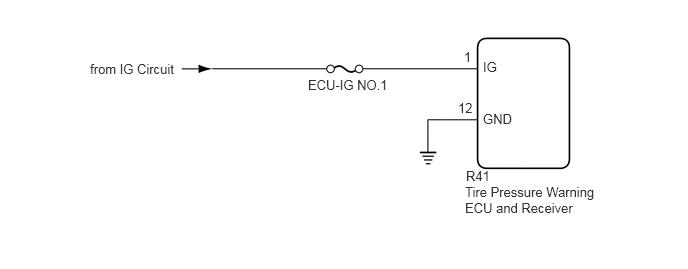
CAUTION / NOTICE / HINT
- NOTICE:
- ·
When replacing the tire pressure warning ECU and receiver, first use the GTS to record all of the current IDs and registered tires with transmitters (4 or 5 tires) of the tire pressure warning valve and transmitter registered to the tire pressure warning ECU and receiver.
·It is necessary to perform initializationSuspension>TIRE PRESSURE MONITORING>TIRE PRESSURE WARNING SYSTEM>INITIALIZATION after registrationSuspension>TIRE PRESSURE MONITORING>TIRE PRESSURE WARNING SYSTEM>REGISTRATION of the transmitter IDs into the tire pressure warning ECU and receiver if the ECU has been replaced.
- HINT:
-
Inspect the fuses for circuits related to this system before performing the following inspection procedure.
PROCEDURE
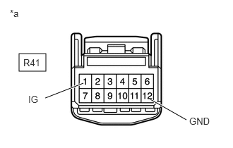
| *a | Front view of wire harness connector
(to Tire Pressure Warning ECU and Receiver) |
Disconnect the R41 tire pressure warning ECU and receiver connector.
Measure the voltage according to the value(s) in the table below.
- Standard Voltage:
Tester Connection Condition Specified Condition R41-1 (IG) - Body ground Ignition switch ON 10 to 16 V Ignition switch off Below 1 V
Measure the resistance according to the value(s) in the table below.
- Standard Resistance:
Tester Connection Condition Specified Condition R41-12 (GND) - Body ground Always Below 1 Ω
- Result:
Proceed to OK NG
OK
for 3 door: Click hereSuspension>TIRE PRESSURE MONITORING>TIRE PRESSURE WARNING RECEIVER (for 3 Door)>REMOVAL
for 5 door: Click hereSuspension>TIRE PRESSURE MONITORING>TIRE PRESSURE WARNING RECEIVER (for 5 Door)>REMOVAL
NG