Home › Steering › STEERING COLUMN › HEATED STEERING WHEEL SYSTEM › from 2017.08
RM27T0E _55 Steering _053718 STEERING COLUMN _0260963 HEATED STEERING WHEEL SYSTEM J

STEERING COLUMN  HEATED STEERING WHEEL SYSTEM  Steering Wheel does not Heat Up When Heated Steering Wheel Switch is Pressed  


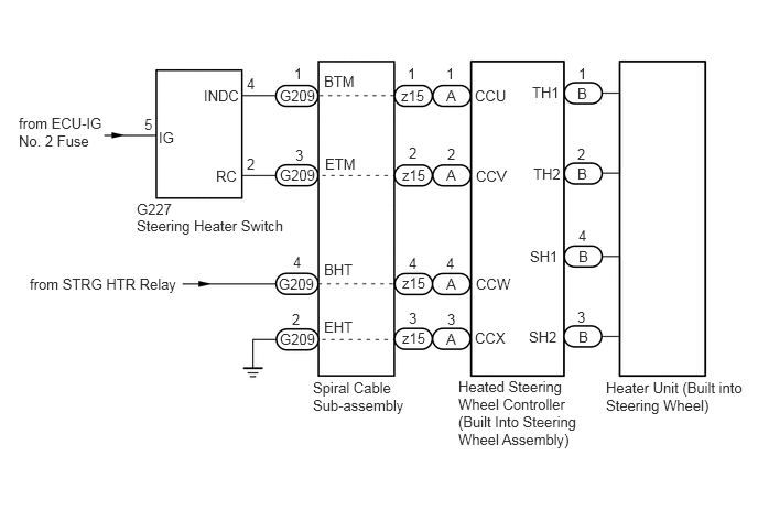
WIRING DIAGRAM

C421842E01
1.292,2.052 2.75,2.26 1.458,0.208 10 false Steering Heater Switch 0.281,2.604 1.875,2.906 1.594,0.302 10 false from STRG HTR Relay 0.177,1.083 1.031,1.458 0.854,0.375 10 false from ECU-IG No. 2 Fuse 4.333,3.573 5.469,4.281 1.135,0.708 10 false Heated Steering Wheel Controller (Built Into Steering Wheel Assembly) 2.646,3.125 3.042,3.344 0.396,0.219 10 false G209 3.063,3.01 3.385,3.188 0.323,0.177 10 false EHT 3.063,0.688 3.385,0.865 0.323,0.177 10 false BTM 2.333,0.708 2.458,0.885 0.125,0.177 10 false 4 1.365,1.094 1.552,1.271 0.188,0.177 10 false 5 2.781,0.615 2.906,0.792 0.125,0.177 10 false 1 2.76,2.938 2.885,3.115 0.125,0.177 10 false 2 2.771,2.396 2.896,2.573 0.125,0.177 10 false 4 2.792,1.385 2.917,1.563 0.125,0.177 10 false 3 5.469,2.146 5.594,2.323 0.125,0.177 10 false 4 5.458,2.917 5.583,3.094 0.125,0.177 10 false 3 5.469,0.615 5.594,0.792 0.125,0.177 10 false 1 5.458,1.375 5.583,1.552 0.125,0.177 10 false 2 2.333,1.469 2.458,1.646 0.125,0.177 10 false 2 3.073,1.469 3.396,1.646 0.323,0.177 10 false ETM 3.063,2.469 3.385,2.646 0.323,0.177 10 false BHT 4.49,0.823 4.813,1 0.323,0.177 10 false CCU 4.5,2.604 4.896,2.781 0.396,0.177 10 false CCW 4.49,3.115 4.813,3.292 0.323,0.177 10 false CCX 4.5,1.583 4.823,1.76 0.323,0.177 10 false CCV 5.031,0.792 5.354,0.969 0.323,0.177 10 false TH1 5.042,1.563 5.365,1.74 0.323,0.177 10 false TH2 5.01,2.344 5.333,2.521 0.323,0.177 10 false SH1 5,3.104 5.323,3.281 0.323,0.177 10 false SH2 5.729,3.583 7.094,4.031 1.365,0.448 10 false Heater Unit (Built into Steering Wheel) 1.5,1.219 1.823,1.396 0.323,0.177 10 false IG 1.927,0.823 2.333,1 0.406,0.177 10 false INDC 2.042,1.583 2.448,1.76 0.406,0.177 10 false RC 2.958,3.583 3.927,3.948 0.969,0.365 10 false Spiral Cable Sub-assembly 1.292,1.896 1.677,2.073 0.385,0.177 10 false G227 2.635,2.604 3.031,2.823 0.396,0.219 10 false G209 2.646,1.573 3.042,1.792 0.396,0.219 10 false G209 2.646,0.823 3.042,1.042 0.396,0.219 10 false G209 3.802,3.115 4.094,3.302 0.292,0.188 10 false z15 3.802,2.594 4.094,2.781 0.292,0.188 10 false z15 3.802,1.573 4.094,1.76 0.292,0.188 10 false z15 3.792,0.823 4.083,1.01 0.292,0.188 10 false z15 4.219,0.823 4.427,1.021 0.208,0.198 10 false A 4.219,1.573 4.427,1.771 0.208,0.198 10 false A 4.219,2.604 4.427,2.802 0.208,0.198 10 false A 4.219,3.125 4.427,3.323 0.208,0.198 10 false A 5.458,0.802 5.667,1 0.208,0.198 10 false B 5.458,1.563 5.667,1.76 0.208,0.198 10 false B 5.469,2.344 5.677,2.542 0.208,0.198 10 false B 5.469,3.104 5.677,3.302 0.208,0.198 10 false B 4.219,0.615 4.344,0.792 0.125,0.177 10 false 1 4.229,1.375 4.354,1.552 0.125,0.177 10 false 2 4.219,2.406 4.344,2.583 0.125,0.177 10 false 4 4.229,2.938 4.354,3.115 0.125,0.177 10 false 3 3.854,0.615 3.979,0.792 0.125,0.177 10 false 1 3.865,1.365 3.99,1.542 0.125,0.177 10 false 2 3.865,2.406 3.99,2.583 0.125,0.177 10 false 4 3.865,2.927 3.99,3.104 0.125,0.177 10 false 3

PROCEDURE

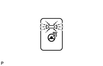
1.CHECK STEERING HEATER SWITCH (LED OPERATION)
C221135

a.

Check the illumination condition of the LED.

Result:
LED Condition Proceed to
Illuminates Engine switch on (IG)
Heated steering wheel switch is pushed
B
Does not illuminate Engine switch on (IG)
Heated steering wheel switch is pushed and held continuously for 10 seconds or more
A


A

2.INSPECT STEERING WHEEL ASSEMBLY (THERMISTOR)

B

3.INSPECT STEERING WHEEL ASSEMBLY (HEATER, THERMOSTAT)
2.INSPECT STEERING WHEEL ASSEMBLY (THERMISTOR)
a.

Disconnect the heated steering wheel controller (built into steering wheel assembly).
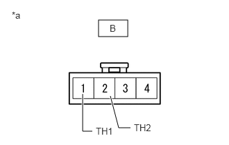

b.
C234543E08
1.479,0.302 1.917,0.552 0.438,0.25 1.958,1.927 1.781,1.927 1.781,1.927 1.656,1.448 true 1.385,1.979 1.24,1.979 1.24,1.979 1.24,1.417 true 0.177,0.146 0.615,0.417 0.438,0.271 10 false *a 1.438,1.896 1.74,2.104 0.302,0.208 10 false TH1 2.01,1.844 2.313,2.052 0.302,0.208 10 false TH2 1.646,0.344 1.854,0.573 0.208,0.229 10 false B

Measure the resistance according to the value(s) in the table below.

Standard Resistance:
Tester Connection Condition Specified Condition
B-1 (TH1) - B-2 (TH2) 10 to 30 °C(50 to 86°F) 8.132 to 18.43 kΩ


Text in Illustration
*a Front view of wire harness connector
(to Heated Steering Wheel Controller)


OK

3.INSPECT STEERING WHEEL ASSEMBLY (HEATER, THERMOSTAT)

NG

REPLACE STEERING WHEEL ASSEMBLY

3.INSPECT STEERING WHEEL ASSEMBLY (HEATER, THERMOSTAT)
a.

Disconnect the heated steering wheel controller (built into steering wheel assembly).
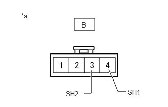

b.
C234543E09
1.521,0.375 1.938,0.615 0.417,0.24 2.583,1.865 2.406,1.865 2.406,1.865 2.229,1.417 true 1.719,1.906 1.865,1.906 1.865,1.906 1.865,1.438 true 0.438,0.24 0.875,0.51 0.438,0.271 10 false *a 2.615,1.802 2.917,2.01 0.302,0.208 10 false SH1 1.344,1.833 1.646,2.042 0.302,0.208 10 false SH2 1.667,0.427 1.969,0.635 0.302,0.208 10 false B

Measure the resistance according to the value(s) in the table below.

Standard Resistance:
Tester Connection Condition Specified Condition
B-3 (SH2) - B-4 (SH1) 20°C (68°F) 1.89 to 2.25 Ω


Text in Illustration
*a Front view of wire harness connector
(to Heated Steering Wheel Controller)


OK

4.CHECK HARNESS AND CONNECTOR (STEERING HEATER SWITCH - SPIRAL CABLE)

NG

REPLACE STEERING WHEEL ASSEMBLY

4.CHECK HARNESS AND CONNECTOR (STEERING HEATER SWITCH - SPIRAL CABLE)
a.

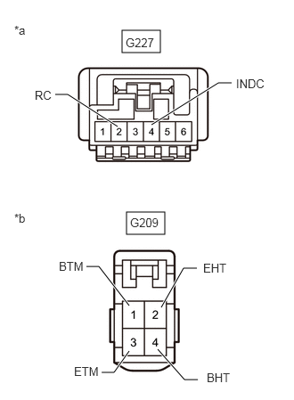
Disconnect the G227 steering heater switch connector.


b.

Disconnect the G209 spiral cable sub-assembly connector.

c.
C420163E01
1.479,2.479 1.927,2.74 0.448,0.26 1.427,0.354 1.875,0.615 0.448,0.26 1.375,1.479 0.792,1.104 0.792,1.104 0.646,1.104 true 1.51,3.573 1.156,3.115 1.156,3.115 1.01,3.115 true 1.51,4.104 1.333,4.354 1.333,4.354 1.188,4.354 true 1.771,1.458 2.552,0.969 2.552,0.969 2.708,0.969 true 1.885,3.594 2.146,3.135 2.146,3.135 2.302,3.135 true 1.844,4.083 2.156,4.438 2.156,4.438 2.313,4.438 true 0.167,0.271 0.479,0.469 0.313,0.198 10 false *a 0.167,2.469 0.479,2.667 0.313,0.198 10 false *b 0.406,1.031 0.719,1.229 0.313,0.198 10 false RC 1.521,2.521 1.885,2.729 0.365,0.208 10 false G209 1.469,0.417 1.844,0.615 0.375,0.198 10 false G227 2.76,0.896 3.115,1.083 0.354,0.188 10 false INDC 2.375,3.052 2.729,3.24 0.354,0.188 10 false EHT 2.417,4.333 2.771,4.521 0.354,0.188 10 false BHT 0.865,4.26 1.219,4.448 0.354,0.188 10 false ETM 0.688,3.031 1.042,3.219 0.354,0.188 10 false BTM

Measure the resistance according to the value(s) in the table below.
Standard Resistance:
Tester Connection Condition Specified Condition
G227-4 (INDC) - G209-1 (BTM) Always Below 1 Ω
G227-2 (RC) - G209-3 (ETM) Always Below 1 Ω
G209-2 (EHT) - Body ground Always Below 1 Ω


Text in Illustration
*a Front view of wire harness connector
(to Steering Heater Switch)
*b Front view of wire harness connector
(to Spiral Cable Sub-assembly)


d.

Measure the voltage according to the value(s) in the table below.

Standard Voltage:
Tester Connection Switch Condition Specified Condition
G209-4 (BHT) - Body ground Engine switch on (IG) 11 to 14 V


OK

5.INSPECT SPIRAL CABLE SUB-ASSEMBLY

NG

REPAIR OR REPLACE WIRE HARNESS OR CONNECTOR

5.INSPECT SPIRAL CABLE SUB-ASSEMBLY
NOTICE:

If there are any defects as mentioned below, replace the spiral cable sub-assembly with a new one:

Scratches, cracks, dents or chips in the connector or spiral cable.


a.

Disconnect the G209 spiral cable sub-assembly connector.


b.

Disconnect the heated steering wheel controller (built into steering wheel assembly).


c.

Measure the resistance according to the value(s) in the table below.

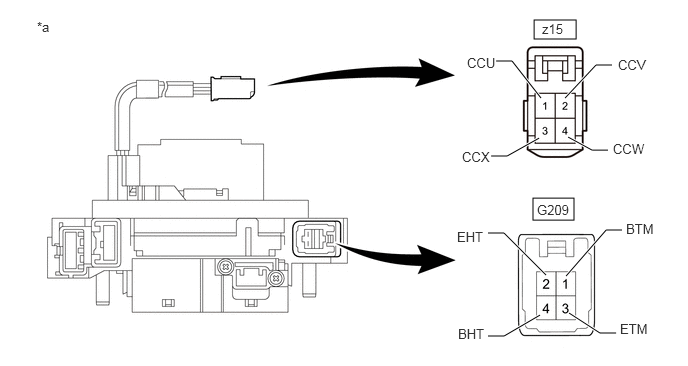
C420164E01
5.552,2.063 5.979,2.292 0.427,0.229 5.563,0.208 6,0.406 0.438,0.198 5.688,2.865 5.25,2.427 5.25,2.427 5.083,2.427 true 5.625,3.281 5.25,3.5 5.25,3.5 5.083,3.5 true 5.927,3.26 6.25,3.469 6.25,3.469 6.417,3.469 true 5.896,2.875 6.313,2.396 6.313,2.396 6.479,2.396 true 5.635,1.021 5.333,0.635 5.333,0.635 5.167,0.635 true 5.885,1.021 6.208,0.677 6.208,0.677 6.375,0.677 true 5.917,1.427 6.167,1.563 6.167,1.563 6.333,1.563 true 5.615,1.438 5.281,1.625 5.281,1.625 5.115,1.625 true 4.865,0.573 5.24,0.771 0.375,0.198 10 false CCU 4.813,1.552 5.188,1.75 0.375,0.198 10 false CCX 6.385,1.469 6.76,1.667 0.375,0.198 10 false CCW 6.438,0.594 6.813,0.792 0.375,0.198 10 false CCV 5.594,2.104 5.958,2.302 0.365,0.198 10 false G209 5.646,0.219 6.01,0.417 0.365,0.198 10 false z15 6.458,3.344 6.833,3.542 0.375,0.198 10 false ETM 6.521,2.302 6.896,2.5 0.375,0.198 10 false BTM 4.771,3.396 5.146,3.594 0.375,0.198 10 false BHT 4.76,2.385 5.135,2.583 0.375,0.198 10 false EHT 0.385,0.198 0.635,0.354 0.25,0.156 10 false *a

Text in Illustration
*a Component without harness connected
(Spiral Cable Sub-assembly)
- -

Standard Resistance:
Tester Connection Condition Specified Condition
z15-1 (CCU) - G209-1 (BTM) Always Below 1 Ω
z15-2 (CCV) - G209-3 (ETM) Always Below 1 Ω
z15-3 (CCX) - G209-2 (EHT) Always Below 1 Ω
z15-4 (CCW) - G209-4 (BHT) Always Below 1 Ω


OK

6.CHECK STEERING HEATER SWITCH

NG

REPLACE SPIRAL CABLE SUB-ASSEMBLY

6.CHECK STEERING HEATER SWITCH
a.

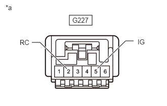
Disconnect the G227 steering heater switch connector.

b.
C420165E01
1.427,0.313 1.896,0.521 0.469,0.208 1.375,1.417 0.823,0.875 0.823,0.875 0.656,0.875 true 2.01,1.406 2.583,0.844 2.583,0.844 2.75,0.844 true 0.406,0.792 0.833,0.948 0.427,0.156 10 false RC 0.115,0.073 0.438,0.313 0.323,0.24 10 false *a 2.833,0.781 3.094,0.938 0.26,0.156 10 false IG 1.49,0.333 1.917,0.5 0.427,0.167 10 false G227

Measure the voltage according to the value(s) in the table below.

HINT:

As the circuit has a diode, perform the measurement in diode test mode and make sure that the polarity is correct.


Standard Voltage:
Tester Connection
Positive (+) tester probe - Negative (-) tester probe
Switch Condition Specified Condition
G227-5 (IG) - G227-2 (RC) Heated steering wheel switch is pushed Below 1.25 V


Text in Illustration
*a Component without harness connected
(to Steering Heater Switch)


OK

REPLACE HEATED STEERING WHEEL CONTROLLER (STEERING WHEEL ASSEMBLY)

NG

REPLACE STEERING HEATER SWITCH