PARK ASSIST / MONITORING MULTI-TERRAIN MONITOR SYSTEM C1612 IG Voltage is Low or High
DESCRIPTION
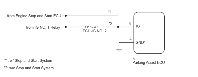
This DTC is stored if the parking assist ECU judges as a result of its self check that the voltage received by terminal IG is low or high.
| DTC Code | DTC Detection Condition | Trouble Area |
|---|---|---|
| C1612 | ·
IG voltage is low ·
IG voltage is high |
·
Harness or connector ·
Parking assist ECU |
WIRING DIAGRAM
CAUTION / NOTICE / HINT
- NOTICE:
- ·
When "!" mark is displayed on the radio and display receiver assembly after the cable is disconnected from the negative (-) battery terminal, correct the steering angle neutral point.
(See page Audio / Visual / Telematics>PARK ASSIST / MONITORING>MULTI-TERRAIN MONITOR SYSTEM>INITIALIZATION).
·Depending on the parts that are replaced or operations that are performed during vehicle inspection or maintenance, calibration of other systems as well as the multi-terrain monitor system may be needed (See page General>SETUP>WHEN REPLACING OR REMOVING/INSTALLING PARTS>WORK PROCEDURE).
·Inspect the fuses for circuits related to this system before performing the following procedure.
PROCEDURE
Clear the DTCs (See page Audio / Visual / Telematics>PARK ASSIST / MONITORING>MULTI-TERRAIN MONITOR SYSTEM>DTC CHECK / CLEAR).
Check for DTCs (See page Audio / Visual / Telematics>PARK ASSIST / MONITORING>MULTI-TERRAIN MONITOR SYSTEM>DTC CHECK / CLEAR).
- OK:
DTC C1612 is not output.
- HINT:
-
If the parking assist ECU cannot read the stored information when it is activated, allowing the ECU to store the information again may return the system to normal.
OK
(See pageGeneral>INTRODUCTION>HOW TO TROUBLESHOOT ECU CONTROLLED SYSTEMS>HOW TO PROCEED WITH TROUBLESHOOTING)
NG
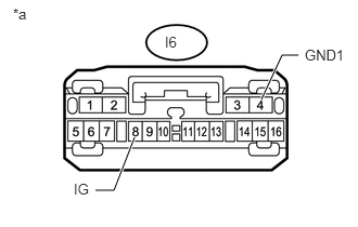
Disconnect the parking assist ECU connector.
Measure the resistance according to the value(s) in the table below.
- Standard Resistance:
Tester Connection Condition Specified Condition I6-4 (GND1) - Body ground Always Below 1 Ω
Measure the voltage according to the value(s) in the table below.
- Standard Voltage:
Tester Connection Switch Condition Specified Condition *1: w/o Stop and Start System
*2: w/ Stop and Start System
I6-8 (IG) - I6-4 (GND1) Engine switch on (IG) 11 to 14 V*1
10.5 to 16 V*2I6-8 (IG) - I6-4 (GND1) Engine switch off Below 1 V
| *a | Front view of wire harness connector
(to Parking Assist ECU) |
OK
for LHD:
(See pageAudio / Visual / Telematics>PARK ASSIST / MONITORING>PARKING ASSIST ECU (for LHD)>REMOVAL)
for RHD:
Click hereAudio / Visual / Telematics>PARK ASSIST / MONITORING>PARKING ASSIST ECU (for RHD)>REMOVAL
NG