2TR-FE BATTERY / CHARGING GENERATOR REMOVAL
CAUTION / NOTICE / HINT
The necessary procedures (adjustment, calibration, initialization or registration) that must be performed after parts are removed, installed or replaced during the generator assembly removal/installation are shown below.
| Replaced Part or Performed Procedure | Necessary Procedure | Effect/Inoperative Function when Necessary Procedure not Performed | Link |
|---|---|---|---|
| Battery terminal is disconnected/reconnected | Correction of steering angle neutral point | Multi-terrain monitor system | ( ) |
- HINT:
-
When the cable is disconnected/reconnected to the auxiliary battery terminal, systems temporarily stop operating. However, each system has a function that completes learning the first time the system is used.
-
Learning completes when vehicle is driven
Effect/Inoperative Function When Necessary Procedures are not Performed Necessary Procedures Link Lane departure alert system Drive the vehicle straight ahead at 40 km/h (25 mph) or more for 10 seconds or more. ( )
Pre-collision system Lighting system (EXT) (for LED Headlight) Stop and start system Drive the vehicle until stop and start control is permitted (approximately 5 to 60 minutes) ( )
Vehicle stability control system (for Hydraulic brake booster) Drive the vehicle straight ahead at 40 km/h (25 mph) or more for at least 10 seconds. ( )
PROCEDURE

 1. PRECAUTION
- NOTICE:
-
After turning the ignition switch off, waiting time may be required before disconnecting the cable from the negative (-) battery terminal.
-
Click hereGeneral>INTRODUCTION>REPAIR INSTRUCTION>PRECAUTION
2.DISCONNECT CABLE FROM NEGATIVE BATTERY TERMINAL
17705
3.REMOVE AIR CLEANER CAP SUB-ASSEMBLY WITH AIR CLEANER HOSE
16361A
4.REMOVE FAN AND GENERATOR V BELT
27020
5.REMOVE GENERATOR ASSEMBLY
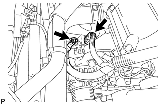
Disconnect the connector from the generator assembly.
Remove the terminal cap.
Remove the nut and disconnect the wire harness from terminal B.
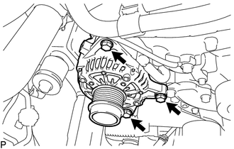
Remove the 3 bolts and generator assembly.