1GD-FTV EMISSION CONTROL UREA TANK INSTALLATION
PROCEDURE

 77862
1.INSTALL NO. 2 UREA TANK BRACKET
Install the No. 2 urea tank bracket to the urea tank sub-assembly with the bolt.
- Torque:
- 14.3 N*m (146 kgf*cm, 11 ft.*lbf)
77861
2.INSTALL NO. 1 UREA TANK BRACKET
Install the No. 1 urea tank bracket to the urea tank sub-assembly with the bolt.
- Torque:
- 14.3 N*m (146 kgf*cm, 11 ft.*lbf)
77903
3.INSTALL UREA TANK BREATHER TUBE SUB-ASSEMBLY
- NOTICE:
-
Check for dirt or mud on the urea tank sub-assembly and around the urea tank breather tube connector before connection. Clean if necessary.
Attach the clamp and install the urea tank breather tube sub-assembly to the urea tank sub-assembly.
- HINT:
-
If there is any solidified urea solution (white solids) on the connection areas of the urea tank breather tube sub-assembly and urea tank sub-assembly, clean the solids off with water. Otherwise, they may prevent the O-ring from sealing properly.
Wash the connection area of the urea tank breather tube connector with water to remove all solidified urea solution (white solids).
Wipe off the connection area of the urea tank sub-assembly with water to remove all solidified urea solution (white solids).
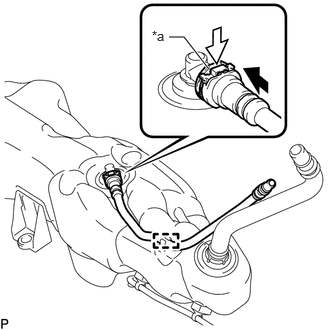
| *a | Retainer |

|
Push |

|
Push Down |
Align the axis of the connector with the axis of the urea tank sub-assembly. Push the urea tank breather tube connector into the urea tank sub-assembly until the urea tank breather tube connector makes a "click" sound.
Push down the retainer.
After connecting the urea tank sub-assembly and the urea tank breather tube connector, check that the urea tank sub-assembly and urea tank breather tube connector are securely connected by trying to pull them apart.
77801
4.INSTALL UREA TANK SUB-ASSEMBLY
Install the urea tank sub-assembly to the frame LH with the 2 bolts.
- Torque:
- 14.3 N*m (146 kgf*cm, 11 ft.*lbf)
77900
5.CONNECT UREA TANK FILLER PIPE WITH SUPPORT ASSEMBLY
- NOTICE:
-
Check for dirt or mud on the urea tank breather tube sub-assembly, urea tank sub-assembly and around the urea tank filler pipe with support connector before connection. Clean if necessary.
Connect the urea tank filler pipe with support assembly to the urea tank breather tube sub-assembly.
- HINT:
-
If there is any solidified urea solution (white solids) on the connection areas of the urea tank filler pipe with support assembly and urea tank breather tube sub-assembly, clean the solids off with water. Otherwise, they may prevent the O-ring from sealing properly.
Wash the connection area of the urea tank filler pipe with support connector with water to remove all solidified urea solution (white solids).
Wipe off the connection area of the urea tank breather tube sub-assembly with water to remove all solidified urea solution (white solids).
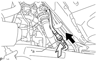
| *a | Retainer |
|
|
Push |
|
|
Push Down |
Align the axis of the connector with the axis of the urea tank breather tube sub-assembly. Push the urea tank filler pipe with support connector into the urea tank breather tube sub-assembly until the urea tank filler pipe with support connector makes a "click" sound.
Push down the retainer.
After connecting the urea tank breather tube sub-assembly and the urea tank filler pipe with support connector, check that the urea tank breather tube sub-assembly and urea tank filler pipe with support connector are securely connected by trying to pull them apart.
Connect the urea tank filler pipe with support assembly to the urea tank sub-assembly.
- HINT:
-
If there is any solidified urea solution (white solids) on the connection areas of the urea tank filler pipe with support assembly and urea tank sub-assembly, clean the solids off with water. Otherwise, they may prevent the O-ring from sealing properly.
Wash the connection area of the urea tank filler pipe with support connector with water to remove all solidified urea solution (white solids).
Wipe off the connection area of the urea tank sub-assembly with water to remove all solidified urea solution (white solids).
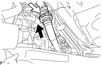
| *a | Retainer |
|
|
Push |
|
|
Push Down |
Align the axis of the connector with the axis of the urea tank sub-assembly. Push the urea tank filler pipe with support connector into the urea tank sub-assembly until the urea tank filler pipe with support connector makes a "click" sound.
Push down the retainer.
After connecting the urea tank sub-assembly and the urea tank filler pipe with support connector, check that the urea tank sub-assembly and urea tank filler pipe with support connector are securely connected by trying to pull them apart.
77840
6.CONNECT UREA TUBE WITH HEATER ASSEMBLY
Attach the 4 clamps and connect the urea tube with heater assembly to the frame crossmember and urea tank sub-assembly.
Connect the urea tube with heater assembly to the urea injector set (See page Engine / Hybrid System>1GD-FTV (EMISSION CONTROL)>UREA INJECTOR>INSTALLATION).
82169
7.CONNECT NO. 3 FRAME WIRE
Attach the 2 clamps and connect the No. 3 frame wire.
53737A
8.INSTALL NO. 1 FRONT FENDER APRON TO FRAME SEAL LH
Install the No. 1 front fender apron to frame seal LH to the body with the 5 clips.
35000
9.INSTALL AUTOMATIC TRANSMISSION ASSEMBLY (for Automatic Transmission)
33030
10.INSTALL MANUAL TRANSMISSION UNIT ASSEMBLY (for Manual Transmission)
77871A
11.INSTALL UREA PUMP