Removal / installation · Vehicles built Sep 2011 – Dec 2011
Versions by build date: Sep 2011 – Dec 2011from Jan 2012
1.
REMOVE FRONT FENDER SPLASH SHIELD SUB-ASSEMBLY RH
HINT:
Use the same procedures described for the LH side.
2.
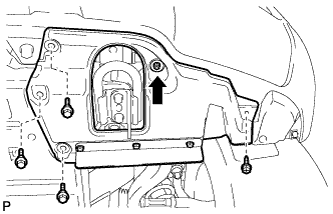
REMOVE FRONT FENDER SPLASH SHIELD SUB-ASSEMBLY LH
Remove the 3 bolts and screw.
Turn the clip indicated by the arrow in the illustration to remove the fender splash shield.
3.
REMOVE NO. 1 ENGINE UNDER COVER SUB-ASSEMBLY
Remove the 10 bolts and engine under cover.
4.
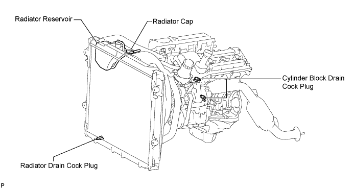
DRAIN ENGINE COOLANT
CAUTION:
Do not remove the radiator cap while the engine and radiator are still hot. Pressurized, hot engine coolant and steam may be released and cause serious burns.
Loosen the radiator drain cock plug and 2 cylinder block drain cock plugs.
Remove the radiator cap. Then drain the coolant.
HINT:
Collect the coolant in a container and dispose of it according to the regulations in your area.
Tighten the 2 cylinder block drain cock plugs.
Torque:
13 N*m{
133 kgf*cm
, 10 ft.*lbf
}
Tighten the radiator drain cock plug by hand.
5.
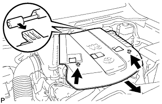
REMOVE V-BANK COVER
Remove the 2 cap nuts and V-bank cover.
6.
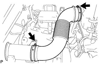
REMOVE NO. 2 AIR CLEANER HOSE
Loosen the 2 hose clamps and remove the air cleaner hose.
7.
REMOVE AIR CLEANER ASSEMBLY
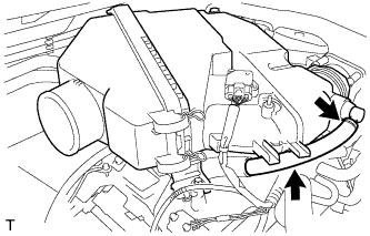
Disconnect the No. 2 ventilation hose.
Detach the hose clamp.
Disconnect the vacuum hose.
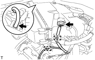
Disconnect the MAF meter connector.
Using a clip remover, detach the 2 wire harness clamps.
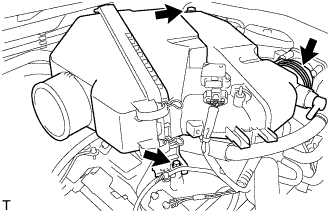
Loosen the hose clamp.
Remove the 2 bolts and air cleaner assembly.
8.
REMOVE THROTTLE BODY WITH MOTOR ASSEMBLY
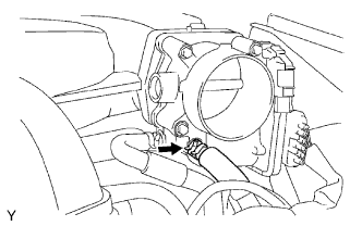
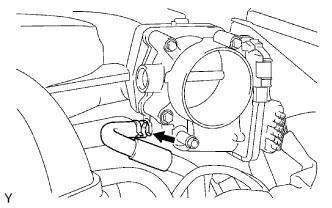
Disconnect the No. 5 water by-pass hose.
Disconnect the No. 4 water by-pass hose.
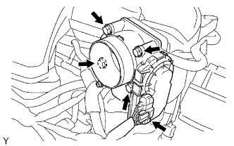
Disconnect the throttle position sensor and throttle control motor connector.
Remove the 4 bolts, then remove the throttle body with motor and gasket.
9.
REMOVE CAMSHAFT TIMING OIL CONTROL VALVE ASSEMBLY (for Bank 1)
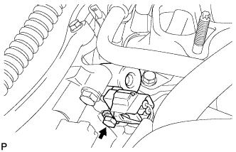
Disconnect the oil control valve connector.
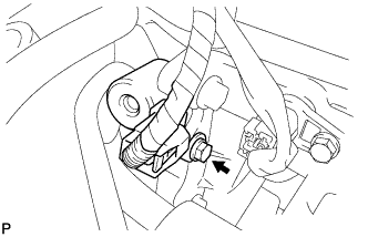
Remove the bolt and oil control valve.
Remove the O-ring from the oil control valve.
10.
REMOVE CAMSHAFT TIMING OIL CONTROL VALVE ASSEMBLY (for Bank 2)