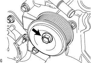
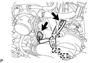
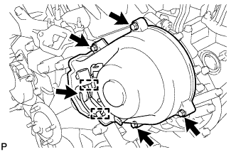
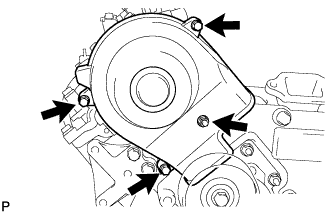
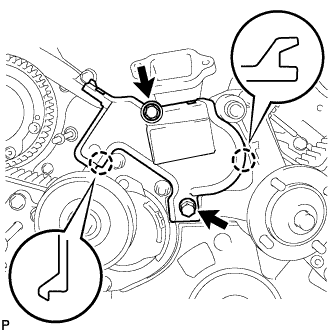
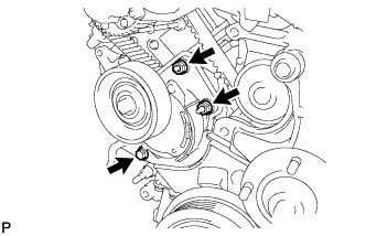
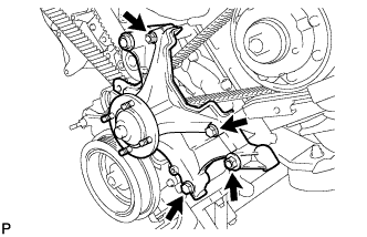
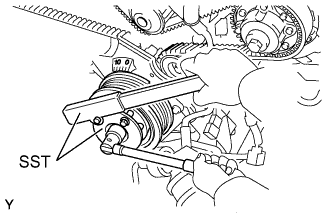
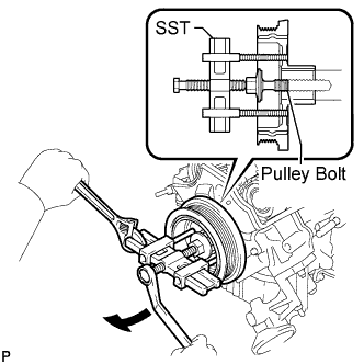
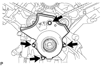
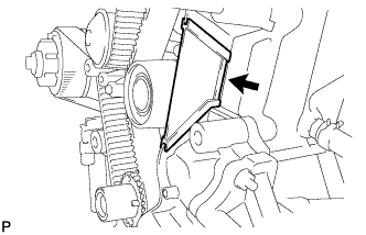
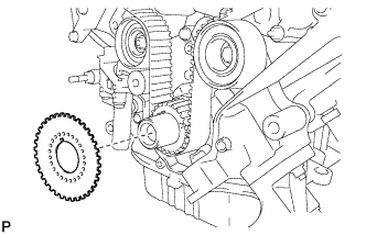
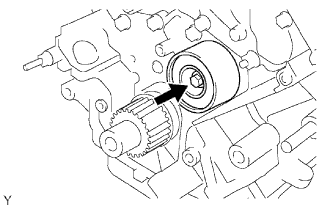
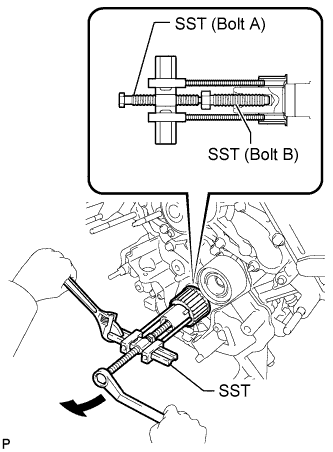
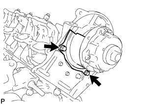
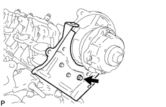
Remove the position sensor plate from the crankshaft.
11.
REMOVE CAMSHAFT POSITION SENSOR ASSEMBLY
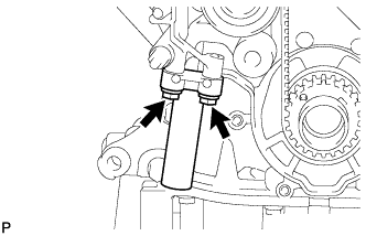
Remove the bolt, stud bolt and camshaft position sensor.
12.
SET NO. 1 CYLINDER TO TDC/COMPRESSION
Temporarily install the pulley bolt.
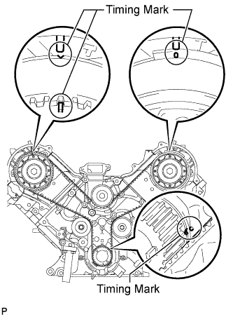
Rotate the crankshaft clockwise so that the timing marks on the crankshaft timing pulley and camshaft timing pulleys are as shown in the illustration.
HINT:
If the timing marks do not align, rotate the crankshaft clockwise again and align the timing marks.
When reusing the timing belt, put a timing mark on the belt where the timing marks on the belt and timing pulley are aligned after rotating the crankshaft.
13.
REMOVE TIMING BELT
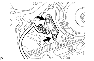
Alternately loosen the 2 bolts, then remove the bolts, timing belt tensioner and dust seal.
Remove the timing belt.
14.
REMOVE NO. 1 TIMING BELT IDLER SUB-ASSEMBLY
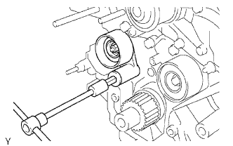
Using a 10 mm hexagon wrench, remove the idler shaft, timing belt idler and plate washer.
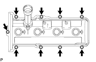
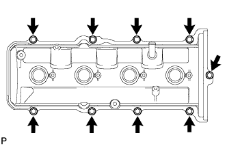
Remove the 9 bolts, cylinder head cover and gasket.
22.
REMOVE CYLINDER HEAD COVER SUB-ASSEMBLY
Remove the 9 bolts, cylinder head cover and gasket.
23.
REMOVE SPARK PLUG TUBE GASKET
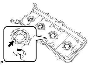
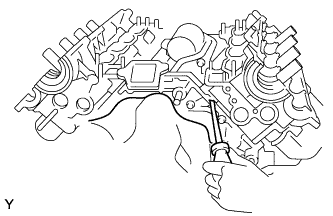
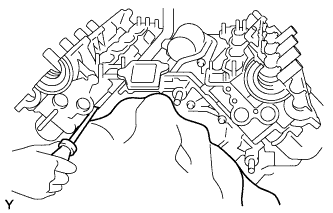
Bend the 8 ventilation case claws of the cylinder head cover to an angle of 90° or more.
Using a screwdriver, pry out the gaskets.
NOTICE:
Be careful not to damage the cylinder head cover.
Be careful not to damage the gasket when removing it, as the removed gasket needs to be reused when installing a new one.
HINT:
Tape the screwdriver tip before use.
24.
REMOVE SEMICIRCULAR PLUG
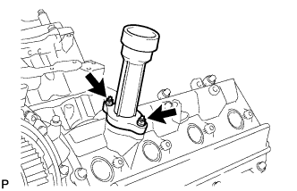
Remove the 4 semicircular plugs from the cylinder heads.
25.
REMOVE CAMSHAFT TIMING PULLEY SUB-ASSEMBLY LH
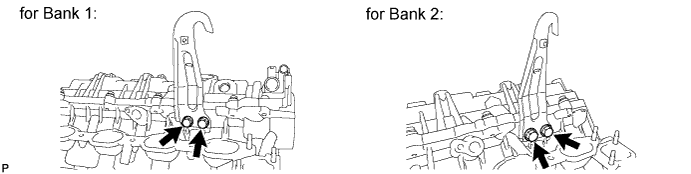
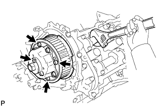
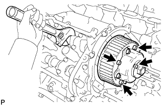
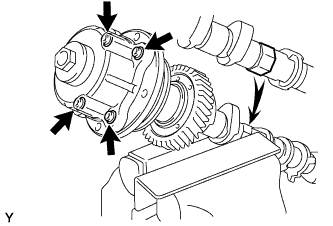
Hold the hexagonal portion of the camshaft with a wrench and remove the 4 bolts indicated by the arrows in the illustration and timing pulley.
NOTICE:
Do not loosen or remove the 4 bolts that are not indicated by the arrows in the illustration. If any of them are loosened or removed, the backlash of the gear in the timing tube will go out of adjustment. In this case, replace the timing tube assembly with a new one.
Be careful not to damage the cylinder head with the wrench.
26.
REMOVE CAMSHAFT TIMING PULLEY
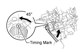
Using the pulley set bolt, turn the crankshaft counterclockwise by approximately 45°.
NOTICE:
If the timing belt is disengaged, having the crankshaft pulley at a wrong angle can cause the piston head and valve head to come into contact with each other when removing the camshaft timing pulley and camshaft, causing damage. So always set the crankshaft pulley at the correct angle.
Hold the hexagonal portion of the camshaft with a wrench and remove the 4 bolts indicated by the arrows in the illustration and timing pulley.
NOTICE:
Do not loosen or remove the 4 bolts that are not indicated by the arrows in the illustration. If any of them are loosened or removed, the backlash of the gear in the timing tube will go out of adjustment. In this case, replace the timing tube assembly with a new one.
Be careful not to damage the cylinder head with the wrench.
27.
REMOVE REAR NO. 2 TIMING BELT PLATE RH
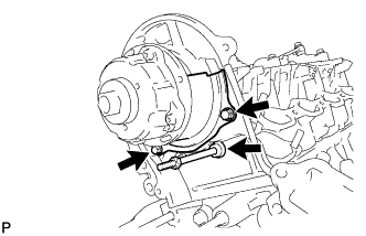
Remove the 2 bolts, stud bolt and timing belt plate.
28.
REMOVE REAR TIMING BELT PLATE RH
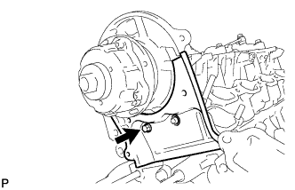
Remove the bolt and rear timing belt plate.
29.
REMOVE REAR NO. 2 TIMING BELT PLATE LH
Remove the 2 bolts and timing belt plate.
30.
REMOVE REAR TIMING BELT PLATE LH
Remove the bolt and rear timing belt plate.
31.
REMOVE CAMSHAFT (for Bank 1)
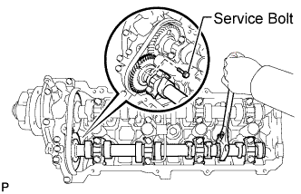
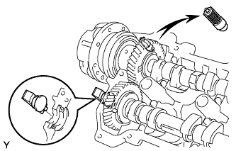
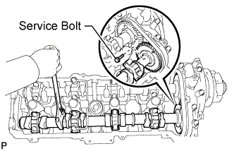
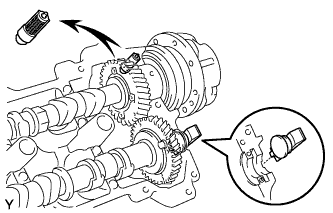
Bring the service bolt hole of the sub-gear upward by turning the hexagonal portion of the exhaust camshaft with a wrench.
Secure the sub-gear to the driven gear with a service bolt.
Recommended Service Bolt:
Thread Diameter
Thread Pitch
Bolt Length
6.0 mm
1.0 mm
16 to 20 mm (0.630 to 0.787 in.)
HINT:
When removing the camshafts, make sure that the torsional spring force of the sub-gear has been eliminated by the above operation.
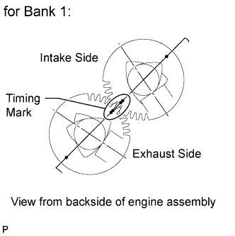
Using a wrench, turn the camshaft so that the timing marks (2 dot marks each) on the camshaft drive and driven gears are aligned, as shown in the illustration.
HINT:
The position shown in the illustration is the most stable position for the exhaust camshaft.
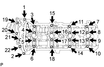
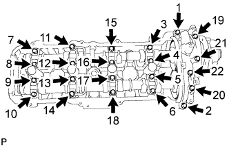
Uniformly loosen and remove the 22 bearing cap bolts in several steps, in the order shown in the illustration.
NOTICE:
As the thrust clearance of the camshaft is small, the camshaft must be kept level while it is being removed. If the camshaft is not kept level, the portion of the cylinder head which receives the shaft thrust may crack or be damaged. To avoid this, the following steps should be carried out.
Remove the cap bolts, 4 seal washers, oil feed pipe, 9 bearing caps, camshaft housing plug, oil control valve filter and camshafts.
NOTICE:
Do not forcibly pry the camshaft with a tool.
Do not damage the reception part of the thrust on the cylinder head side.
HINT:
Arrange the bearing caps in the correct order.
32.
REMOVE CAMSHAFT (for Bank 2)
Bring the service bolt hole of the sub-gear upward by turning the hexagonal portion of the exhaust camshaft with a wrench.
Secure the sub-gear to the driven gear with a service bolt.
Recommended Service Bolt:
Thread Diameter
Thread Pitch
Bolt Length
6.0 mm
1.0 mm
16 to 20 mm (0.630 to 0.787 in.)
HINT:
When removing the camshafts, make sure that the torsional spring force of the sub-gear has been eliminated by the above operation.
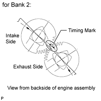
Using a wrench, turn the camshaft so that the timing marks (1 dot mark each) on the camshaft drive and driven gears are aligned, as shown in the illustration.
HINT:
The position shown in the illustration is the most stable position for the exhaust camshaft.
Uniformly loosen and remove the 22 bearing cap bolts in several steps, in the order shown in the illustration.
NOTICE:
As the thrust clearance of the camshaft is small, the camshaft must be kept level while it is being removed. If the camshaft is not kept level, the portion of the cylinder head which receives the shaft thrust may crack or be damaged. To avoid this, the following steps should be carried out.
Remove the cap bolts, 4 seal washers, oil feed pipe, 9 bearing caps, camshaft housing plug, oil control valve filter and camshafts.
NOTICE:
Do not forcibly pry the camshaft with a tool.
Do not damage the reception part of the thrust on the cylinder head side.
HINT:
Arrange the bearing caps in the correct order.
33.
REMOVE VALVE LIFTER
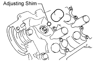
Remove the valve lifters and adjusting shims from the cylinder head.
HINT:
Arrange the removed parts in the correct order.
34.
REMOVE CYLINDER HEAD LH
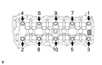
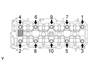
Uniformly loosen the 10 cylinder head bolts on the cylinder head in several passes, in the sequence shown in the illustration.
Remove the bolts and plate washers.
NOTICE:
Cylinder head warpage or cracking could result from removing bolts in the incorrect order.
Do not drop the plate washer for the cylinder head bolt of the cylinder head.
Remove the cylinder head by prying between the cylinder block and cylinder head with a screwdriver.
NOTICE:
Be careful not to damage the contact surfaces of the cylinder head and cylinder block.
The cylinder head should not be tilted so as to secure the valve lifter. If the cylinder head is tilted, remove the valve lifter and check that the adjusting shim is set correctly.
35.
REMOVE CYLINDER HEAD GASKET LH
36.
REMOVE CYLINDER HEAD SUB-ASSEMBLY
Uniformly loosen the 10 cylinder head bolts on the cylinder head in several passes, in the sequence shown in the illustration.
Remove the bolts and plate washers.
NOTICE:
Cylinder head warpage or cracking could result from removing bolts in the incorrect order.
Do not drop the plate washer for the cylinder head bolt of the cylinder head.
Remove the cylinder head by prying between the cylinder block and cylinder head with a screwdriver.
NOTICE:
Be careful not to damage the contact surfaces of the cylinder head and cylinder block.
The cylinder head should not be tilted so as to secure the valve lifter. If the cylinder head is tilted, remove the valve lifter and check that the adjusting shim is set correctly.
37.
REMOVE CYLINDER HEAD GASKET RH
38.
REMOVE CAMSHAFT TIMING TUBE ASSEMBLY
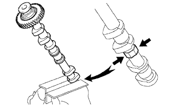
Mount the hexagonal portion of the camshaft in a vise.
NOTICE:
Be careful not to damage the camshaft.
Do not loosen or remove the 4 bolts shown in the illustration. If any of them are loosened or removed, the backlash of the gear in the timing tube will go out of adjustment. In this case, replace the timing tube assembly with a new one.
Remove the screw plug and seal washer.
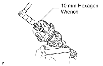
Using a 10 mm hexagon wrench, remove the bolt and timing tube.
39.
REMOVE CAMSHAFT DRIVE GEAR
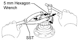
Using SST and a 5 mm hexagon wrench, remove the 4 bolts, drive gear and oil seal.
SST
09960-10010
(09962-01000, 09963-00500)
NOTICE:
Be careful not to damage the timing tube.
40.
REMOVE CAMSHAFT SUB-GEAR
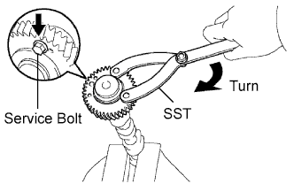
Mount the hexagonal portion of the camshaft in a vise.
NOTICE:
Be careful not to damage the camshaft.
Using SST, turn the sub-gear clockwise, and remove the service bolt.
SST
09960-10010
(09962-01000, 09963-00500)
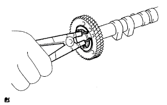
Using snap ring pliers, remove the snap ring.
Remove the wave washer, sub-gear and gear spring.
HINT:
Arrange the camshaft sub-gears and gear spring (LH and RH).
41.
REMOVE WATER PUMP ASSEMBLY
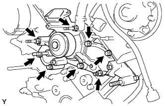
Remove the 5 bolts, 2 stud bolts, nut, water pump and gasket.
Remove the O-ring from the water by-pass pipe.
42.
REMOVE OIL PRESSURE SENDER GAUGE ASSEMBLY
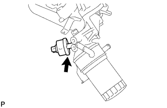
Disconnect the sender gauge connector.
Remove the sender gauge.
43.
REMOVE OIL FILTER BRACKET SUB-ASSEMBLY
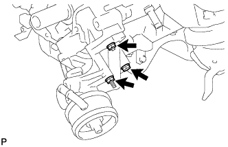
Remove the bolt, nut, stud bolt, oil filter bracket and gasket.
44.
REMOVE NO. 2 OIL PAN SUB-ASSEMBLY
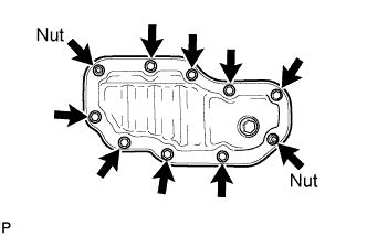
Remove the 8 bolts and 2 nuts.
Insert the blade of an oil pan seal cutter between the oil pans, cut off applied sealer and remove the No. 2 oil pan.
NOTICE:
Be careful not to damage the No. 2 oil pan contact surface of the oil pan.
Be careful not to damage the No. 2 oil pan flange.
45.
REMOVE OIL PAN SUB-ASSEMBLY
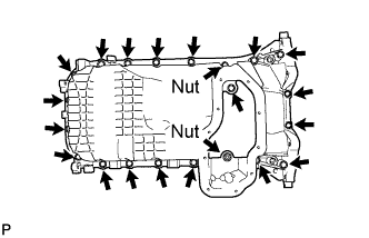
Remove the 19 bolts and 2 nuts.
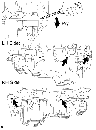
Using a screwdriver, remove the oil pan by prying between the oil pan and cylinder block as shown in the illustration.
NOTICE:
Be careful not to damage the contact surfaces of the cylinder block and oil pan.
46.
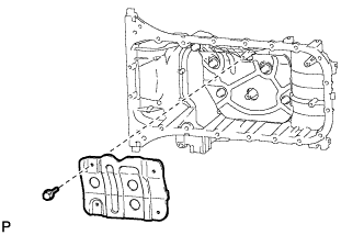
REMOVE NO. 1 OIL PAN BAFFLE PLATE
Remove the 4 bolts and baffle plate.
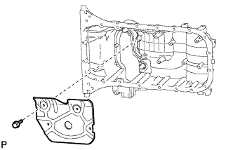
47.
REMOVE NO. 2 OIL PAN BAFFLE PLATE
Remove the 4 bolts and baffle plate.
48.
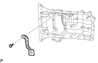
REMOVE NO. 3 OIL PAN BAFFLE PLATE
Remove the 2 bolts and baffle plate.
49.
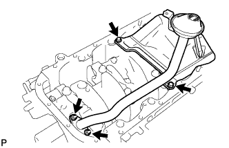
REMOVE OIL STRAINER SUB-ASSEMBLY
Remove the 2 bolts, 2 nuts, oil strainer and gasket.
50.
REMOVE OIL PUMP ASSEMBLY
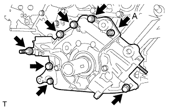
Using a 6 mm hexagon wrench, remove bolt A.
Remove the 6 bolts and stud bolt.
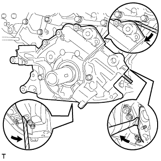
Using a screwdriver, remove the oil pump by prying the portions between the oil pump and cylinder block shown in the illustration.
NOTICE:
Be careful not to damage the contact surfaces of the cylinder block and oil pump.
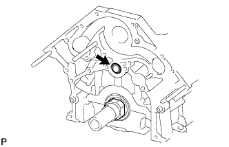
Remove the O-ring from the cylinder block.
51.
REMOVE OIL PUMP SEAL
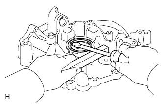
Using a screwdriver and wooden block, pry out the oil seal.
NOTICE:
Do not damage the surface of the oil seal press fit hole.
52.
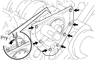
REMOVE ENGINE REAR OIL SEAL RETAINER
Remove the 7 bolts.
Using a screwdriver, remove the oil seal retainer by prying in between the oil seal retainer and crankshaft bearing cap.
Remove the O-ring.
53.
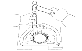
REMOVE ENGINE REAR OIL SEAL
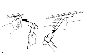
Place the rear oil seal retainer on wooden blocks.
Using a screwdriver and hammer, tap out the oil seal.
NOTICE:
Do not damage the surface of the oil seal press fit hole.
54.
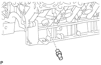
REMOVE CYLINDER BLOCK WATER DRAIN COCK SUB-ASSEMBLY
Remove the 2 drain cock plugs from the drain cock.