INSPECTION
Inspection · Vehicles built Sep 2011 – Dec 2011
| INSPECT EXHAUST MANIFOLD SUB-ASSEMBLY LH |

Using a precision straightedge and feeler gauge, measure the warpage of the contact surface between the cylinder head and exhaust manifold.
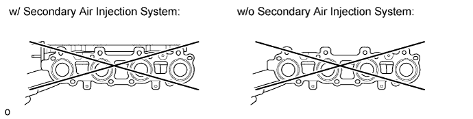

- Maximum warpage:
- 0.50 mm (0.0197 in.)
| INSPECT EXHAUST MANIFOLD SUB-ASSEMBLY RH |
Using a precision straightedge and feeler gauge, measure the warpage of the contact surface between the cylinder head and exhaust manifold.
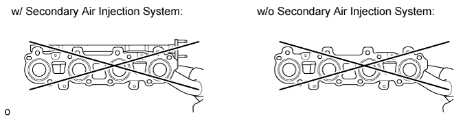
- Maximum warpage:
- 0.50 mm (0.0197 in.)
| INSPECT CYLINDER HEAD SET BOLT |
Using a vernier caliper, measure the thread outside diameter of the bolt.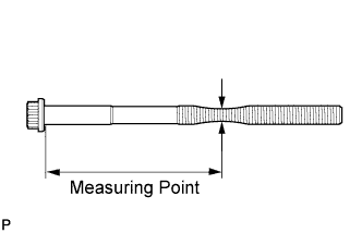
- Measuring Point:
Item
Specified Condition
Intake side
82 mm (3.23 in.)
Exhaust side
86 mm (3.39 in.)
- Standard outside diameter:
- 9.810 to 9.960 mm (0.386 to 0.392 in.)
- Minimum outside diameter:
- 9.700 mm (0.382 in.)
- HINT:
- If a visual check reveals no excessively thin areas, check the center of the bolt (see illustration) and find the area that has the minimum diameter.
| INSPECT CAMSHAFT |
Inspect the circle runout.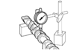
Place the camshaft on V-blocks.
Using a dial indicator, measure the circle runout at the center journal.
- Standard circle runout:
- 0 to 0.06 mm (0 to 0.00236 in.)
- Maximum circle runout:
- 0.08 mm (0.00315 in.)
Inspect the cam lobes.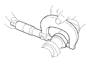
Using a micrometer, measure the cam lobe height.
- Standard Cam Lobe Height:
Item
Specified Condition
Intake
42.61 to 42.71 mm (1.6776 to 1.6815 in.)
Exhaust
42.63 to 42.73 mm (1.6783 to 1.6823 in.)
- Minimum Cam Lobe Height:
Item
Specified Condition
Intake
42.46 mm (1.6717 in.)
Exhaust
42.48 mm (1.6724 in.)
Inspect the camshaft journals.
Using a micrometer, measure the journal diameter.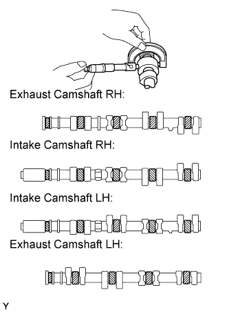
- Standard journal diameter:
- 26.954 to 26.970 mm (1.061 to 1.062 in.)
Using a micrometer, measure the journal diameter for the camshaft timing tube.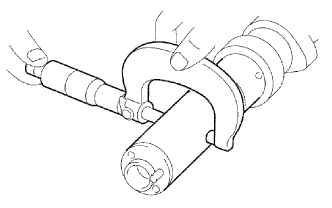
- Standard journal diameter:
- 30.984 to 31.000 mm (1.2198 to 1.2204 in.)
| INSPECT CAMSHAFT TIMING TUBE ASSEMBLY |
Using a micrometer, measure the journal diameter.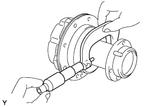
- Standard journal diameter:
- 39.955 to 39.964 mm (1.5730 to 1.5734 in.)
Install the camshaft timing tube to the camshaft (Click here).
Check the lock of the camshaft timing tube.
Check that the camshaft timing tube is locked.
Release the lock pin.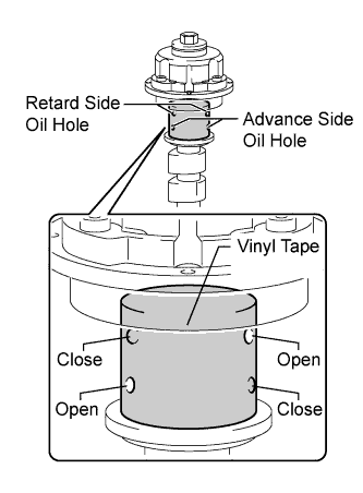
Clean the camshaft timing tube journal with non-residue solvent.
Wrap tape around the entire journal to block the 4 oil holes as shown in the illustration.
Open a hole in the tape at 2 places, one in the retard side oil hole and one in the advance side oil hole as shown in the illustration.
Apply approximately 200 kPa (2.0 kgf/cm2, 29 psi) of air pressure to the 2 open oil holes (the advance side oil hole and the retard side oil hole).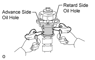
- NOTICE:
- Cover the oil holes with a piece of cloth when applying pressure to keep oil from splashing.
- HINT:
- The lock pin will be released when air pressure is applied.
Check that the camshaft timing tube revolves in the advance direction when reducing the air pressure applied to the retard side oil hole.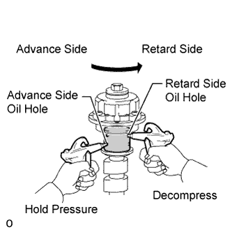
When the camshaft timing tube reaches the most advanced position, release the air pressure from the retard side oil hole and advance side oil hole, in that order.
- NOTICE:
- Do not release the air pressure from the advance side oil hole first. The tube may abruptly shift in the retard direction and break the lock pin.
- When releasing the air pressure from the retard side oil hole, do not release the air pressure too quickly to prevent damage.
- Do not release the air pressure from the advance side oil hole first. The tube may abruptly shift in the retard direction and break the lock pin.
Check for smooth rotation.
Apply 60 kPa (0.6 kgf/cm2, 8.7 psi) of air pressure to the retard side oil hole to release the lock pin.
Turn the camshaft timing tube within its movable range (21°) 2 or 3 times, but do not turn it to the most retarded position. Make sure that the camshaft timing tube turns smoothly.
- NOTICE:
- Do not use air pressure to perform the smooth rotation check. Always perform the check by hand.
Check the lock in the most retarded position.
Confirm that the camshaft timing tube is locked at the most retarded position.
Remove the camshaft timing tube (Click here).
| INSPECT CAMSHAFT GEAR SPRING |
Using a vernier caliper, measure the gap distance of the gear spring.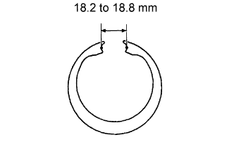
- Standard gap distance:
- 18.2 to 18.8 mm (0.717 to 0.740 in.)
| INSPECT FAN BRACKET SUB-ASSEMBLY |
Check that the fan bracket turns smoothly by turning it.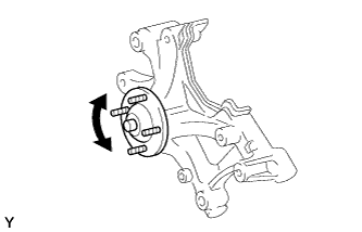
If necessary, replace the fan bracket.
| INSPECT TIMING BELT |
Visually check the timing belt for excessive wear, frayed cords, etc.
If necessary, replace the timing belt.- NOTICE:
-
Do not bend or twist the timing belt or turn it inside out.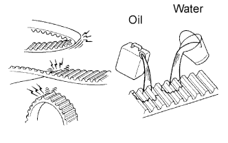
- Do not allow the timing belt to come into contact with oil, water or steam.
-
| INSPECT TIMING BELT TENSIONER ASSEMBLY |
Visually check the seal portion of the tensioner for oil leakage.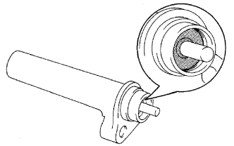
If leakage is found, replace the timing belt tensioner assembly.- HINT:
- If there is only a faint trace of oil on the push rod, the tensioner does not need to be replaced.
Hold the tensioner with both hands and push the push rod strongly as shown to check that it does not move.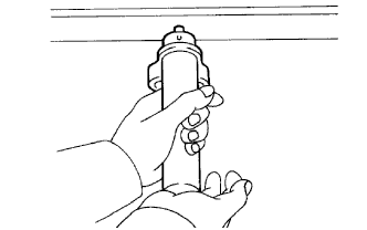
If the push rod moves, replace the timing belt tensioner assembly.- NOTICE:
- Never face the tensioner push rod downward.
Measure the protrusion of the push rod from the housing end.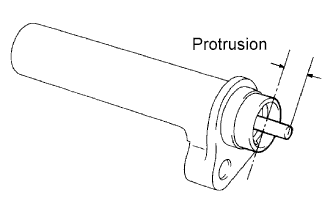
- Standard protrusion:
- 9.5 to 10.5 mm (0.374 to 0.413 in.)
| INSPECT VALVE LIFTER |
Using a micrometer, measure the lifter diameter at a position 12.3 to 12.7 mm (0.484 to 0.500 in.) from the top surface.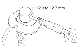
- Standard lifter diameter:
- 30.968 to 30.976 mm (1.2192 to 1.2195 in.)
Using a caliper gauge, measure the lifter bore diameter of the cylinder head.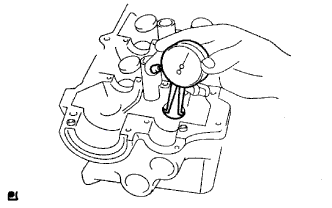
- Standard lifter bore diameter:
- 31.000 to 31.016 mm (1.220 to 1.221 in.)
Subtract the lifter diameter measurement from the lifter bore diameter measurement.
- Standard oil clearance:
- 0.024 to 0.050 mm (0.000945 to 0.00197 in.)
- Maximum oil clearance:
- 0.07 mm (0.00276 in.)
| INSPECT CYLINDER HEAD SUB-ASSEMBLY |
Using a precision straightedge and feeler gauge, measure the surfaces contacting the cylinder block and manifolds for warpage.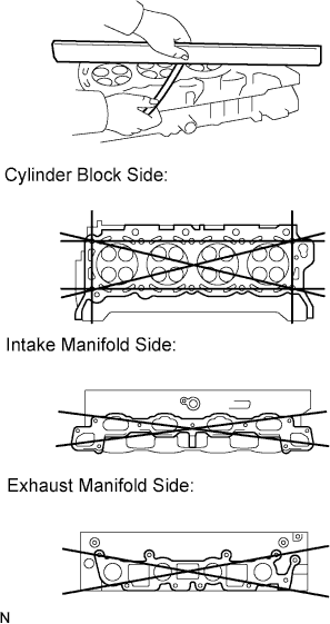
- Standard Warpage:
Item
Specified Condition
Cylinder block side
0 to 0.05 mm (0 to 0.00197 in.)
Intake manifold side
0 to 0.08 mm (0 to 0.00315 in.)
Exhaust manifold side
0 to 0.08 mm (0 to 0.00315 in.)
- Maximum warpage:
- 0.10 mm (0.00394 in.)
- If the warpage is more than the maximum, replace the cylinder head sub-assembly.
Using a dye penetrant, check the combustion chamber, intake ports, exhaust ports and cylinder block surface for cracks.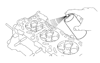
If the cylinder head is cracked, replace it.
| INSPECT CYLINDER BLOCK SUB-ASSEMBLY |
Clean the cylinder block.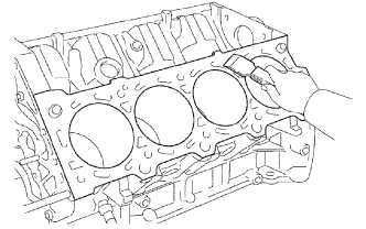
Using a gasket scraper, remove all the gasket material from the top surface of the cylinder block.
Using a soft brush and solvent, thoroughly clean the cylinder block.
- NOTICE:
- If the cylinder is washed at high temperatures, the cylinder liner sticks out beyond the cylinder block. Always wash the cylinder block at a temperature of 45°C (113°F) or less.
Using a precision straightedge and feeler gauge, measure the surfaces contacting the cylinder head and main bearing cap for warpage.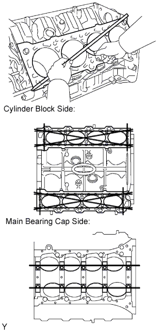
- Standard warpage:
- 0 to 0.05 mm (0 to 0.00197 in.)
- Maximum warpage:
- 0.07 mm (0.00276 in.)
Visually check the cylinder for vertical scratches.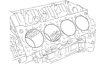
If deep scratches are present, rebore all 8 cylinders and replace all 8 pistons. If necessary, replace the cylinder block.