REMOVAL
Removal / installation · Vehicles built Sep 2011 – Dec 2011
| 1. REMOVE ENGINE OIL LEVEL DIPSTICK GUIDE |

Remove the dipstick.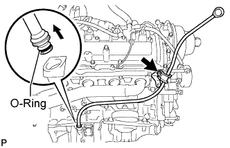

Remove the bolt and dipstick guide.
Remove the O-ring from the dipstick guide.
| 2. REMOVE NO. 3 AIR TUBE (w/ Secondary Air Injection System) |
Remove the 2 bolts, 2 nuts and No. 3 air tube.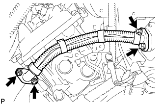
Remove the 2 gaskets.
| 3. REMOVE AIR TUBE SUB-ASSEMBLY RH (w/ Secondary Air Injection System) |
Remove the 2 bolts, 2 nuts and air tube sub-assembly.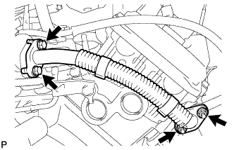
Remove the 2 gaskets.
| 4. REMOVE EXHAUST MANIFOLD SUB-ASSEMBLY RH (w/ Secondary Air Injection System) |
Remove the 8 nuts and exhaust manifold.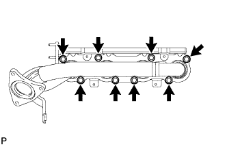
Remove the gasket from the cylinder head RH.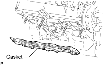
| 5. REMOVE EXHAUST MANIFOLD SUB-ASSEMBLY LH (w/ Secondary Air Injection System) |
Remove the 8 nuts and exhaust manifold.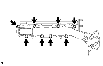
Remove the gasket from the cylinder head LH.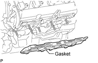
| 6. REMOVE EXHAUST MANIFOLD SUB-ASSEMBLY RH (w/o Secondary Air Injection System) |
Remove the 8 nuts and exhaust manifold.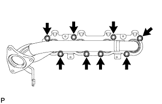
Remove the gasket from the cylinder head RH.
| 7. REMOVE EXHAUST MANIFOLD SUB-ASSEMBLY LH (w/o Secondary Air Injection System) |
Remove the 8 nuts and exhaust manifold.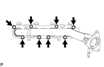
Remove the gasket from the cylinder head LH.
| 8. REMOVE NO. 2 WIRING HARNESS HEAT INSULATOR |
Remove the 2 bolts and No. 2 wiring harness heat insulator.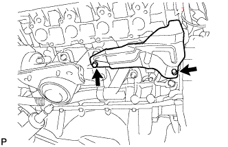
| 9. REMOVE FRONT ENGINE MOUNTING INSULATOR |
Remove the nut and engine mounting insulator.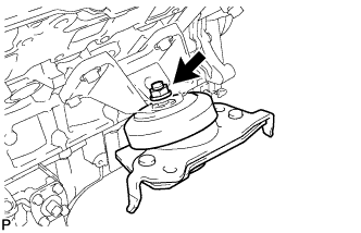
| 10. REMOVE FRONT ENGINE MOUNTING INSULATOR LH |
Remove the nut and engine mounting insulator LH.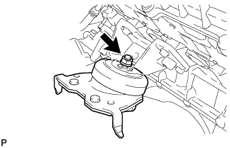
| 11. REMOVE FRONT NO. 1 ENGINE MOUNTING BRACKET RH |
Remove the 4 bolts and No. 1 engine mounting bracket RH.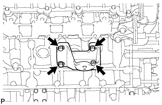
| 12. REMOVE FRONT NO. 1 ENGINE MOUNTING BRACKET LH |
Remove the 4 bolts and No. 1 engine mounting bracket LH.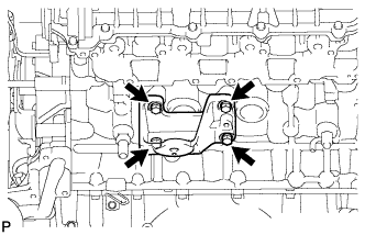
| 13. REMOVE OIL COOLER HOSE |
Using needle-nose pliers, grip the claws of the clamps and slide the clamps to remove the oil cooler hose.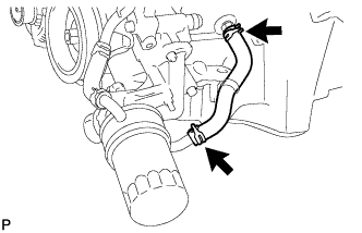
| 14. REMOVE OIL COOLER PIPE |
Remove the cap nut and bolt.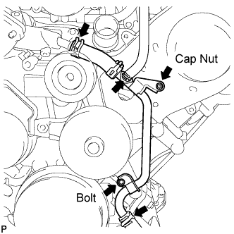
Using needle-nose pliers, grip the claws of the clamps and slide the clamps to disconnect the 3 water by-pass hoses and remove the oil cooler pipe.
| 15. REMOVE OIL FILTER ASSEMBLY |
Using SST, remove the oil filter.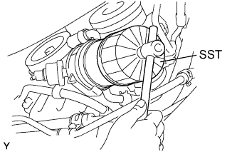
- SST
- 09228-07501
| 16. REMOVE INTAKE MANIFOLD |
Remove the intake manifold (Click here).
| 17. REMOVE IGNITION COIL ASSEMBLY |
Disconnect the 8 ignition coil connectors.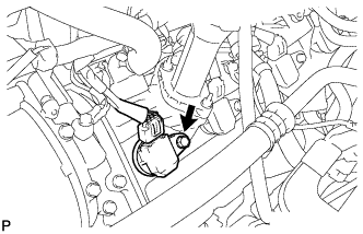
Remove the 8 bolts and pull out the 8 ignition coils.
| 18. DISCONNECT ENGINE WIRE |
Remove the bolt and disconnect the ground wire from the No. 5 bearing cap.
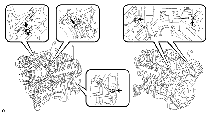
Remove the bolt and disconnect the ground wire from the left side of the engine.
Remove the 2 bolts and disconnect the 2 ground wires from the cylinder head and cylinder head LH rear side.
Remove the bolt and disconnect the ground wire from the inside left side of the V-bank.
| 19. REMOVE WATER INLET HOUSING |
Remove the 2 bolts holding the water inlet housing to the water pump.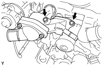
Disconnect the water inlet housing from the front water by-pass joint and water pump. Then remove the water inlet and inlet housing assembly.
Remove the O-ring from the water inlet housing.
| 20. REMOVE ENGINE COOLANT TEMPERATURE SENSOR |
Disconnect the sensor connector.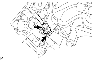
Using a 19 mm deep socket wrench, remove the sensor and gasket.
| 21. REMOVE FRONT WATER BY-PASS JOINT |
Remove the 4 nuts, front water by-pass joint and 2 gaskets.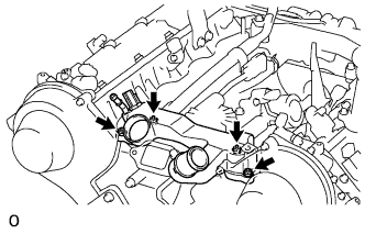
| 22. REMOVE WATER BY-PASS PIPE SUB-ASSEMBLY |
Disconnect the connector.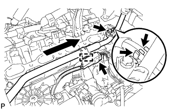
Disconnect the wire harness clamp from the water by-pass pipe.
Disconnect the 2 vacuum switching valve hoses from the water by-pass pipe clamp.
Remove the bolt.
Pull out the water by-pass pipe.
Remove the O-ring from the water by-pass pipe.
| 23. REMOVE NO. 2 AIR SWITCHING VALVE ASSEMBLY (w/ Secondary Air Injection System) |
Remove the vacuum switching valve hose from the No. 2 air switching valve.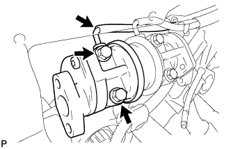
Remove the 2 bolts, gasket and No. 2 air switching valve from the rear water by-pass joint.
| 24. REMOVE NO. 1 AIR SWITCHING VALVE ASSEMBLY (w/ Secondary Air Injection System) |
Remove the vacuum switching valve hose from the No. 1 air switching valve.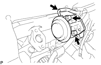
Remove the 2 bolts, gasket and No. 1 air switching valve from the rear water by-pass joint.
| 25. REMOVE NO. 2 AIR INJECTION SYSTEM HOSE (w/ Secondary Air Injection System) |
Remove the No. 2 air injection system hose from the rear water by-pass joint and air switching valve.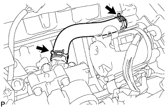
| 26. REMOVE AIR PUMP WITH BRACKET AND AIR SWITCHING VALVE (w/ Secondary Air Injection System) |
Disconnect the air switching valve connector.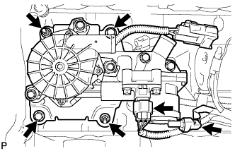
Disconnect the air pressure sensor connector.
Remove the 2 bolts, 2 nuts and air pump with bracket.
| 27. REMOVE REAR WATER BY-PASS JOINT |
Remove the 4 nuts, water by-pass joint and 2 gaskets.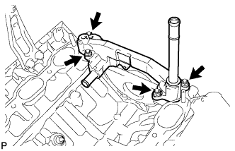
| 28. REMOVE STARTER ASSEMBLY |
Remove the 2 bolts holding the starter to the cylinder block.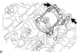
Disconnect the starter from the cylinder block.
Remove the bolt and disconnect the engine wire protector from the starter.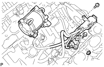
Remove the bolt and disconnect the ground wire.
Disconnect the starter connector.
Remove the nut and disconnect the starter wire.
Remove the starter.
| 29. REMOVE CRANKSHAFT POSITION SENSOR |
Disconnect the sensor connector.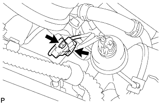
Remove the bolt and sensor.
| 30. REMOVE ENGINE OIL LEVEL SENSOR |
Disconnect the oil level sensor connector.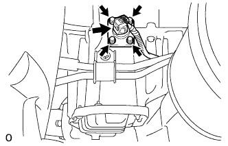
Remove the 4 bolts and oil level sensor.
Cut off the gasket as shown in the illustration.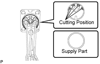
Remove the gasket from the oil level sensor.
- HINT:
- After cutting away the parts of the gasket shown in the illustration, remove only the outer part of the gasket.
| 31. REMOVE CAMSHAFT TIMING OIL CONTROL VALVE ASSEMBLY RH |
Disconnect the oil control valve connector.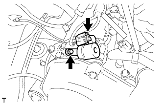
Remove the bolt and camshaft timing oil control valve.
Remove the O-ring from the camshaft timing oil control valve.
| 32. REMOVE CAMSHAFT TIMING OIL CONTROL VALVE ASSEMBLY LH |
Disconnect the oil control valve connector and wire harness clamp.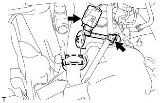
Remove the bolt and camshaft timing oil control valve.
Remove the O-ring from the camshaft timing oil control valve.
| 33. REMOVE VENTILATION VALVE COVER |
Remove the ventilation valve cover from the ventilation valve.
| 34. REMOVE VENTILATION VALVE SUB-ASSEMBLY |
Remove the ventilation valve from the cylinder head cover sub-assembly LH.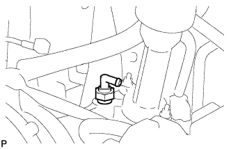
| 35. REMOVE CAMSHAFT POSITION SENSOR |
Disconnect the 2 sensor connectors.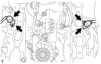
Remove the 2 bolts and 2 sensors.
| 36. REMOVE KNOCK CONTROL SENSOR |
Disconnect the 2 sensor connectors.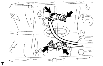
Remove the 2 nuts and 2 sensors.