REASSEMBLY
Removal / installation · Vehicles built Sep 2011 – Dec 2011
| 1. INSTALL CYLINDER BLOCK UNION |

Apply seal packing to 2 or 3 threads of the cylinder block union.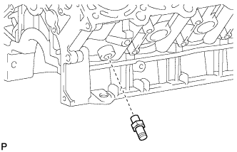

- Seal packing:
- Toyota Genuine Seal Packing 1282B, Three Bond 1282B or equivalent
Install the union to the cylinder block.
- Torque:
- 49 N*m{ 500 kgf*cm , 36 ft.*lbf }
- NOTICE:
- Install the cylinder block union within 3 minutes and tighten the union within 15 minutes after applying seal packing.
| 2. INSTALL CYLINDER BLOCK WATER DRAIN COCK SUB-ASSEMBLY |
Apply seal packing to 2 or 3 threads of the drain cock.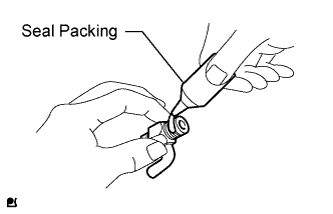
- Seal packing:
- Toyota Genuine Seal Packing 1282B, Three Bond 1282B or equivalent
Install the 2 drain cocks as shown in the illustration.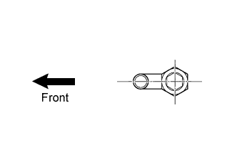
- Torque:
- 49 N*m{ 500 kgf*cm , 36 ft.*lbf }
- NOTICE:
- Do not rotate the drain cocks more than 1 revolution (360°) after tightening the drain cocks to the specified torque.
- Do not loosen the drain cocks to adjust them. If an adjustment is necessary, remove the drain cocks and reinstall them.
- Do not rotate the drain cocks more than 1 revolution (360°) after tightening the drain cocks to the specified torque.
Install the 2 drain cock plugs to the drain cock.
- Torque:
- 13 N*m{ 130 kgf*cm , 9 ft.*lbf }
| 3. INSTALL ENGINE REAR OIL SEAL |
Place the oil seal retainer on wooden blocks.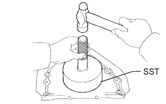
Using SST and a hammer, tap in a new oil seal until its surface is flush with the rear oil seal retainer edge.
- SST
- 09223-56010
- NOTICE:
- Do not tap on the oil seal at an angle.
Apply MP grease to the lip of the oil seal.
- NOTICE:
- Do not allow foreign matter to contact the lip of the oil seal.
- Do not allow MP grease to contact the dust seal.
- Do not allow foreign matter to contact the lip of the oil seal.
| 4. INSTALL ENGINE REAR OIL SEAL RETAINER |
Apply seal packing to the oil seal retainer as shown in the illustration.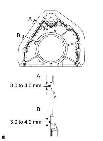
- Seal packing:
- Toyota Genuine Seal Packing Black, Three Bond 1207B or equivalent
- Standard seal diameter:
- 3.0 to 4.0 mm (0.118 to 0.157 in.)
- NOTICE:
- Install the oil seal retainer within 3 minutes and tighten the bolts within 15 minutes after applying seal packing.
- Be careful not to drop any oil on the contact surfaces of the oil seal retainer and cylinder block.
- Install the oil seal retainer within 3 minutes and tighten the bolts within 15 minutes after applying seal packing.
Install a new O-ring to the cylinder block.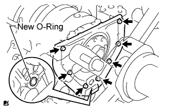
Install the oil seal retainer with the 7 bolts.
- Torque:
- 8.0 N*m{ 82 kgf*cm , 71 in.*lbf }
- NOTICE:
- Do not expose the seal to engine oil for at least an hour after installing it.
| 5. INSTALL OIL PUMP SEAL |
Place the oil pump on a wooden block.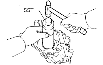
Using SST and a hammer, tap in a new oil seal until its surface is flush with the oil pump body edge.
- SST
- 09316-60011
(09316-00011)
- NOTICE:
- Do not tap the oil seal at an angle.
Apply MP grease to the lip of the oil seal.
- NOTICE:
- Do not allow foreign matter to contact the lip of the oil seal.
- Do not allow MP grease to contact the dust seal.
- Do not allow foreign matter to contact the lip of the oil seal.
| 6. INSTALL OIL PUMP ASSEMBLY |
Apply a light coat of engine oil to a new O-ring and install it to the cylinder block.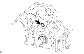
Align the oil pump drive rotor spline and the crankshaft as shown in the illustration.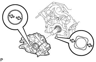
Apply seal packing to the oil pump as shown in the illustration.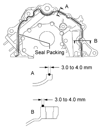
- Seal packing:
- Toyota Genuine Seal Packing Black, Three Bond 1207B or equivalent
- Standard seal diameter:
- 3.0 to 4.0 mm (0.118 to 0.157 in.)
- NOTICE:
- Install the oil pump within 3 minutes and tighten the bolts within 15 minutes after applying seal packing.
- Be careful not to drop any oil on the contact surfaces of the oil pump and cylinder block.
- Do not expose the seal to engine oil for at least 2 hours after installing it.
- Install the oil pump within 3 minutes and tighten the bolts within 15 minutes after applying seal packing.
Install the oil pump with the stud bolt, 6 standard bolts and the 6 mm hexagon wrench bolt. Uniformly tighten the bolts in several steps.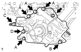
- Torque:
- for bolt A, B, C, E:
- 16 N*m{ 163 kgf*cm , 12 ft.*lbf }
- for bolt D:
- 31 N*m{ 316 kgf*cm , 23 ft.*lbf }
- Bolt Length:
Item
Bolt Head Size
Length
Bolt A
12 mm
35 mm (1.38 in.)
Bolt B
12 mm
50 mm (1.97 in.)
Bolt C
14 mm
103 mm (4.06 in.)
Bolt D
14 mm
44 mm (1.73 in.)
Bolt E
6 mm hexagon
28 mm (1.10 in.)
| 7. INSTALL OIL STRAINER SUB-ASSEMBLY |
Install a new gasket and the oil strainer with the 2 bolts and 2 nuts.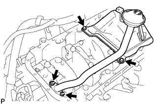
- Torque:
- 8.0 N*m{ 82 kgf*cm , 71 in.*lbf }
| 8. INSTALL NO. 3 OIL PAN BAFFLE PLATE |
Install the baffle plate with the 2 bolts.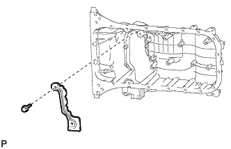
- Torque:
- 7.5 N*m{ 76 kgf*cm , 66 in.*lbf }
| 9. INSTALL NO. 2 OIL PAN BAFFLE PLATE |
Install the baffle plate with the 4 bolts.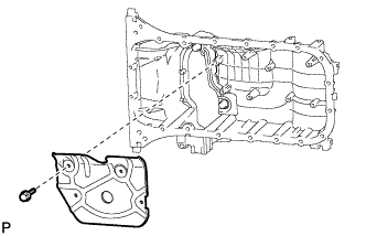
- Torque:
- 7.5 N*m{ 76 kgf*cm , 66 in.*lbf }
| 10. INSTALL NO. 1 OIL PAN BAFFLE PLATE |
Install the baffle plate with the 4 bolts.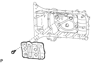
- Torque:
- 7.5 N*m{ 76 kgf*cm , 66 in.*lbf }
| 11. INSTALL OIL PAN SUB-ASSEMBLY |
Apply seal packing to the oil pan as shown in the illustration.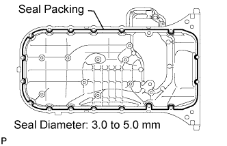
- Seal packing:
- Toyota Genuine Seal Packing Black, Three Bond 1207B or equivalent
- Standard seal diameter:
- 3.0 to 5.0 mm (0.118 to 0.197 in.)
- NOTICE:
- Install the oil pan within 3 minutes and tighten the bolts within 15 minutes after applying seal packing.
- Be careful not to drop any oil on the contact surfaces of the oil pan and cylinder block.
- Do not expose the seal to engine oil for at least 2 hours after installing it.
- Install the oil pan within 3 minutes and tighten the bolts within 15 minutes after applying seal packing.
Temporarily install the oil pan with the 19 bolts and 2 nuts.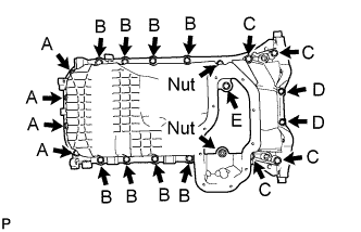
- Bolt Length:
Item
Bolt Head Size
Length
Bolt A
10 mm
22 mm (0.866 in.)
Bolt B
12 mm
25 mm (0.984 in.)
Bolt C
12 mm
60 mm (2.36 in.)
Bolt D
10 mm
35 mm (1.38 in.)
Bolt E
10 mm
22 mm (0.866 in.)
- NOTICE:
- Make sure the rear ends of the oil pan and cylinder block are aligned. If not, the oil pan may become damaged.
Uniformly tighten the bolts and nuts in several passes.
- Torque:
- for bolt A, D, E:
- 7.5 N*m{ 76 kgf*cm , 66 in.*lbf }
- for bolt B, C, nut:
- 28 N*m{ 286 kgf*cm , 21 ft.*lbf }
| 12. INSTALL NO. 2 OIL PAN SUB-ASSEMBLY |
Apply seal packing to the No. 2 oil pan as shown in the illustration.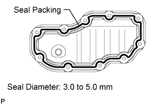
- Seal packing:
- Toyota Genuine Seal Packing Black, Three Bond 1207B or equivalent
- Standard seal diameter:
- 3.0 to 5.0 mm (0.118 to 0.197 in.)
- NOTICE:
- Install the oil pan within 3 minutes and tighten the bolts within 15 minutes after applying seal packing.
- Be careful not to drop any oil on the contact surfaces of the oil pan and No. 2 oil pan.
- Do not expose the seal to engine oil for at least 2 hours after installing it.
- Install the oil pan within 3 minutes and tighten the bolts within 15 minutes after applying seal packing.
Install the No. 2 oil pan with the 8 bolts and 2 nuts. Uniformly tighten the bolts and nuts in several passes.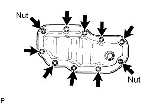
- Torque:
- 7.5 N*m{ 76 kgf*cm , 66 in.*lbf }
| 13. INSTALL OIL FILTER BRACKET SUB-ASSEMBLY |
Install a new gasket to the oil filter bracket.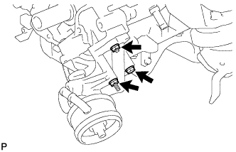
Install the oil filter bracket with the bolt, stud bolt and nut.
- Torque:
- 18 N*m{ 184 kgf*cm , 13 ft.*lbf }
| 14. INSTALL OIL PRESSURE SENDER GAUGE ASSEMBLY |
Apply adhesive to 2 or 3 threads of the sender gauge.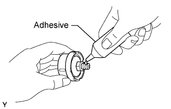
- Adhesive:
- Toyota Genuine Adhesive 1344, Three Bond 1344 or equivalent
- NOTICE:
- Do not let adhesive adhere to the oil hole.
Install the sender gauge.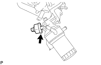
- Torque:
- 15 N*m{ 153 kgf*cm , 11 ft.*lbf }
- NOTICE:
- Do not start the engine within 1 hour of installation.
Connect the sender gauge connector.
| 15. INSTALL WATER PUMP ASSEMBLY |
Apply soapy water to a new O-ring.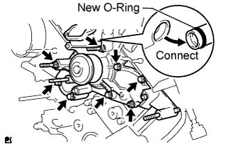
Install the O-ring to the water by-pass pipe end.
Install a new gasket to the cylinder block.
Connect the water pump to the water by-pass pipe end.
Temporarily install the water pump with the 5 bolts, 2 stud bolts and nut. Uniformly tighten the bolts, stud bolts and nut in several passes.
- Torque:
- for bolt:
- 21 N*m{ 214 kgf*cm , 15 ft.*lbf }
- for stud bolt, nut:
- 18 N*m{ 184 kgf*cm , 13 ft.*lbf }
| 16. INSTALL CYLINDER HEAD GASKET LH |
Clean the cylinder block and cylinder head with solvent.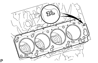
Place a new cylinder head gasket in position on the cylinder block.
- HINT:
- A mark is placed on the rear side of the cylinder head gasket to distinguish the LH and RH sides, a "2R" mark for the RH side and a "2L" mark for the LH side.
- NOTICE:
- Be careful of the installation direction.
| 17. INSTALL CYLINDER HEAD LH |
- HINT:
- The cylinder head bolts are tightened in 3 progressive steps.
Check that the timing mark of the crankshaft timing pulley is in the position shown in the illustration, and that the piston is below the TDC of compression.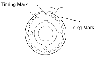
Install the cylinder head with the exhaust manifold to the cylinder block.
- NOTICE:
- Ensure that no oil is on the mounting surface of the cylinder head.
Apply a light coat of engine oil to the threads and under the heads of the cylinder head bolts.
Step 1:
Set the plate washer to the cylinder head bolt.
Install and uniformly tighten the 10 cylinder head bolts and plate washers in the sequence shown in the illustration.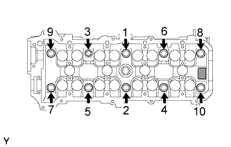
- Torque:
- 40 N*m{ 408 kgf*cm , 30 ft.*lbf }
- NOTICE:
- Do not drop the plate washer for the cylinder head bolt of the cylinder head.
Step 2:
Mark the cylinder head bolt head with paint as shown in the illustration.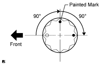
Tighten the cylinder head bolts 90° in the sequence shown in step 1.
Step 3:
Tighten the cylinder head bolts another 90° in the sequence shown in step 1.
Check that the painted marks are now facing rearward.
| 18. INSTALL CYLINDER HEAD GASKET |
Clean the cylinder block and cylinder head with solvent.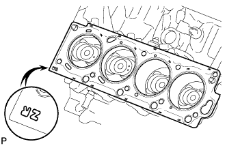
Place a new cylinder head gasket in position on the cylinder block.
- HINT:
- A mark is placed on the rear side of the cylinder head gasket to distinguish the LH and RH sides, a "2R" mark for the RH side and a "2L" mark for the LH side.
- NOTICE:
- Be careful of the installation direction.
| 19. INSTALL CYLINDER HEAD SUB-ASSEMBLY |
- HINT:
- The cylinder head bolts are tightened in 3 progressive steps.
Install the cylinder head with the exhaust manifold to the cylinder block.
- NOTICE:
- Ensure that no oil is on the mounting surface of the cylinder head.
Apply a light coat of engine oil to the threads and under the heads of the cylinder head bolts.
Step 1:
Set the plate washer to the cylinder head bolt.
Install and uniformly tighten the 10 cylinder head bolts and plate washers in the sequence shown in the illustration.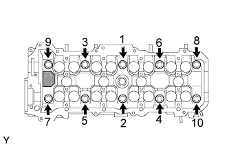
- Torque:
- 40 N*m{ 408 kgf*cm , 30 ft.*lbf }
- NOTICE:
- Do not drop the plate washer for the cylinder head bolt of the cylinder head.
Step 2:
Mark the cylinder head bolt head with paint as shown in the illustration.
Tighten the cylinder head bolts 90° in the sequence shown in step 1.
Step 3:
Tighten the cylinder head bolts another 90° in the sequence shown in step 1.
Check that the painted marks are now facing rearward.
| 20. INSTALL CAMSHAFT SETTING OIL SEAL |
Apply MP grease to the lip of a new oil seal.
- NOTICE:
- Do not allow foreign matter to contact the lip of the oil seal.
- Do not allow MP grease to contact the dust seal.
- Do not allow foreign matter to contact the lip of the oil seal.
Insert the oil seal into the camshaft timing tube until it reaches the stopper.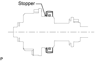
- NOTICE:
- Be careful of the installation direction.
- Do not turn over the lip of the oil seal.
- Be careful of the installation direction.
| 21. INSTALL CAMSHAFT DRIVE GEAR |
Align the timing tube knock pin with the knock pin groove of the drive gear, and temporarily install the drive gear with the 4 bolts.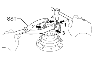
Using SST and a 5 mm hexagon wrench, uniformly tighten the 4 bolts in several steps, in the sequence shown in the illustration.
- Torque:
- 7.5 N*m{ 76 kgf*cm , 66 in.*lbf }
- SST
- 09960-10010
(09962-01000, 09963-00500)
- NOTICE:
- Be careful not to damage the timing tube.
| 22. INSTALL CAMSHAFT TIMING TUBE ASSEMBLY |
Mount the hexagonal portion of the camshaft in a vise.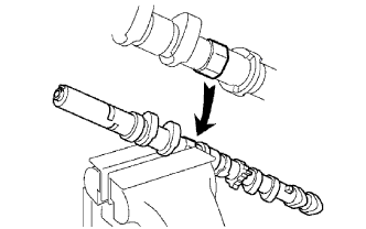
- NOTICE:
- Be careful not to damage the camshaft.
Apply a light coat of engine oil to the camshaft and camshaft timing tube.
Align the camshaft knock pin with the knock pin hole of the timing tube, and push the timing tube by hand until the camshaft knock pin touches the bottom of the timing tube knock pin hole.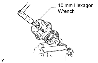
- NOTICE:
- Do not forcefully push on the camshaft timing tube. This may cause the camshaft knock pin tip to damage the installation surface of the camshaft timing tube.
Using a 10 mm socket hexagon wrench, install the bolt.
- Torque:
- 78 N*m{ 795 kgf*cm , 58 ft.*lbf }
Install the seal washer and screw plug.
- Torque:
- 15 N*m{ 153 kgf*cm , 11 ft.*lbf }
| 23. INSTALL CAMSHAFT SUB-GEAR |
Install the gear spring, sub-gear and wave washer.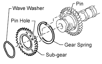
- HINT:
- Attach the pins on the gears to the gear spring ends.
Using snap ring pliers, install the snap ring.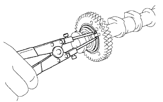
Mount the hexagonal portion of the camshaft in a vise.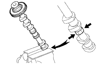
- NOTICE:
- Be careful not to damage the camshaft.
Using SST, align the holes of the driven gear and sub-gear by turning the sub-gear clockwise, and temporarily install a service bolt.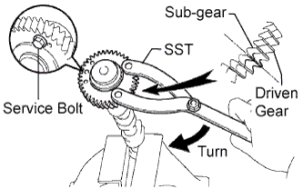
- SST
- 09960-10010
(09962-01000, 09963-00500)
- Recommended Service Bolt:
Thread Diameter
Thread Pitch
Bolt Length
6 mm
1.0 mm
16 to 20 mm (0.630 to 0.787 in.)
Align the gear teeth of the driven gear and sub-gear, and tighten the service bolt.
| 24. INSTALL VALVE LIFTER |
Apply a light coat of engine oil to the valve lifters, adjusting shims and valve stem tips.
Install the valve lifters and adjusting shims.
- NOTICE:
- Be careful not to drop the adjusting shim into the cylinder head.
| 25. INSTALL CAMSHAFT (for Bank 2) |
- NOTICE:
- As the thrust clearance of the camshaft is small, the camshaft must be kept level while it is being installed. If the camshaft is not kept level, the portion of the cylinder head which receives the shaft thrust may crack or be damaged. To avoid this, the following steps should be carried out.
- HINT:
- When performing this procedure to adjust the valve clearance, it is not necessary to apply seal packing to the No. 1 bearing cap and camshaft housing plug.
Apply a light coat of engine oil to the cam lobe and gear of the camshaft and the journal of the cylinder head.
Using a wrench, align the timing marks (1 dot mark each) of the camshaft drive and driven gears, and set the camshaft and No. 2 camshaft in place.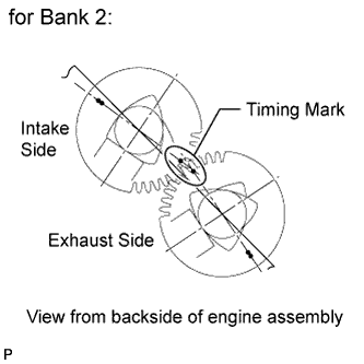
- HINT:
- The position shown in the illustration is the most stable position for the exhaust camshaft.
Apply seal packing to the camshaft housing plug groove.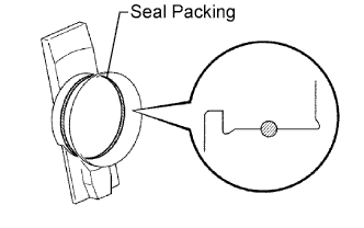
- HINT:
- Remove any old packing (FIPG) material before applying new seal packing.
- Seal packing:
- Toyota Genuine Seal Packing Black, Three Bond 1207B or equivalent
- NOTICE:
- Be careful of the installation direction.
- Remove any oil from the contact surface.
- Be careful of the installation direction.
Install the camshaft housing plug and oil control valve filter to the cylinder head as shown in the illustration.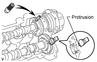
- HINT:
- Align the protrusion on the camshaft housing plug with the groove of the cylinder head and install the plug.
Apply seal packing to the No. 1 bearing cap as shown in the illustration.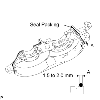
- Seal packing:
- Toyota Genuine Seal Packing Black, Three Bond 1207B or equivalent
- Standard seal diameter:
- 1.5 to 2.0 mm (0.0591 to 0.0787 in.)
- NOTICE:
- Install the No. 1 bearing cap and housing plug within 3 minutes.
Install a new seal washer to each bearing cap bolt indicated by an arrow in the illustration, and apply engine oil to the threads of the bolts. Then temporarily install them.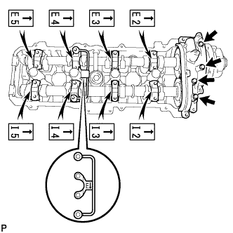
Apply engine oil to the threads and washer part of the bearing cap bolts not indicated in the illustration.
Temporarily install the oil feed pipe and bearing caps with the 18 bearing cap bolts, as shown in the illustration.
- Bolt Length:
Item
Length
Bolt A with seal washer
94 mm (3.70 in.)
Bolt B with seal washer
72 mm (2.84 in.)
Bolt C
25 mm (0.984 in.)
Bolt D
55 mm (2.17 in.)
Bolt E
40 mm (1.58 in.)
- HINT:
- Face the arrow imprinted on the oil feed pipe to the exhaust side.
Push in the camshaft setting oil seal.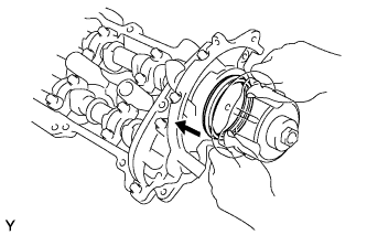
Uniformly tighten the 22 bearing cap bolts in several steps, in the sequence shown in the illustration.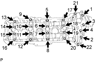
- Torque:
- for bolt 21, 22:
- 7.5 N*m{ 76 kgf*cm , 66 in.*lbf }
- for other bolt:
- 16 N*m{ 163 kgf*cm , 12 ft.*lbf }
Bring the service bolt installed in the driven sub-gear upward by turning the hexagonal portion of the camshaft with a wrench.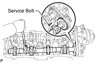
Remove the service bolt.
| 26. INSTALL CAMSHAFT (for Bank 1) |
- NOTICE:
- As the thrust clearance of the camshaft is small, the camshaft must be kept level while it is being installed. If the camshaft is not kept level, the portion of the cylinder head which receives the shaft thrust may crack or be damaged. To avoid this, the following steps should be carried out.
- HINT:
- When performing this procedure to adjust the valve clearance, it is not necessary to apply seal packing to the No. 5 bearing cap and camshaft housing plug.
Check that the timing mark of the crankshaft timing pulley is in the position shown in the illustration, and that the piston is below the TDC of compression.
- NOTICE:
- Having the crankshaft pulley at a wrong angle can cause the piston head and valve head to come into contact with each other when removing the camshaft. Always set the crankshaft pulley at the correct angle as shown in the illustration.
Apply a light coat of engine oil to the cam lobe and gear of the camshaft and the journal of the cylinder head.
Using a wrench, align the timing marks (2 dot marks each) of the camshaft drive and driven gears, and set the No. 3 and No. 4 camshafts in place.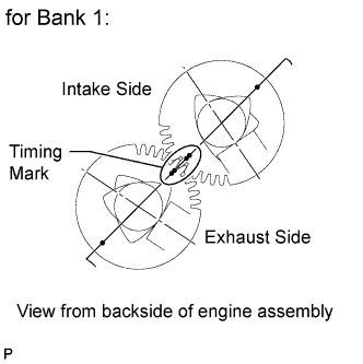
- HINT:
- The position shown in the illustration is the most stable position for the exhaust camshaft.
Apply seal packing to the camshaft housing plug groove.
- HINT:
- Remove any old packing (FIPG) material before applying new seal packing.
- Seal packing:
- Toyota Genuine Seal Packing Black, Three Bond 1207B or equivalent
- NOTICE:
- Be careful of the installation direction.
- Remove any oil from the contact surface.
- Be careful of the installation direction.
Install the camshaft housing plug and oil control valve filter to the cylinder head as shown in the illustration.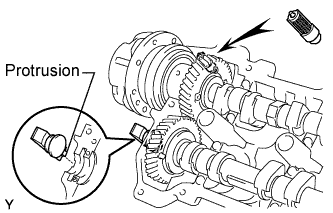
- HINT:
- Align the protrusion on the camshaft housing plug with the groove of the cylinder head and install the plug.
Apply seal packing to the No. 5 bearing cap as shown in the illustration.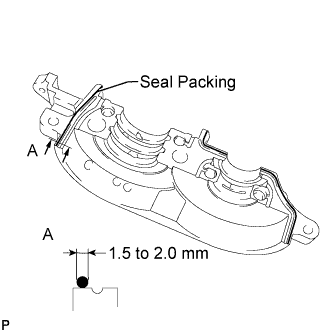
- Seal packing:
- Toyota Genuine Seal Packing Black, Three Bond 1207B or equivalent
- Standard seal diameter:
- 1.5 to 2.0 mm (0.0591 to 0.0787 in.)
- NOTICE:
- Install the No. 5 bearing cap and housing plug within 3 minutes.
Install a new seal washer to each bearing cap bolt indicated by an arrow in the illustration, and apply engine oil to the threads of the bolts. Then temporarily install them.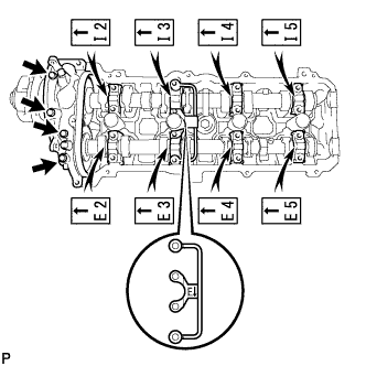
Apply engine oil to the threads and washer part of the bearing cap bolts not indicated in the illustration.
Temporarily install the oil feed pipe and bearing caps with the 18 bearing cap bolts, as shown in the illustration.
- Bolt Length:
Item
Length
Bolt A with seal washer
94 mm (3.70 in.)
Bolt B with seal washer
72 mm (2.84 in.)
Bolt C
25 mm (0.984 in.)
Bolt D
55 mm (2.17 in.)
Bolt E
40 mm (1.58 in.)
- HINT:
- Face the arrow imprinted on the oil feed pipe to the exhaust side.
Push in the camshaft setting oil seal.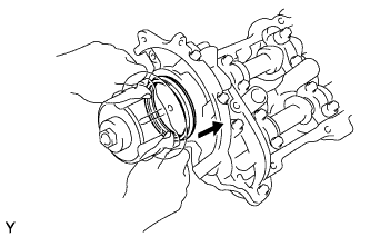
Uniformly tighten the 22 bearing cap bolts in several steps, in the sequence shown in the illustration.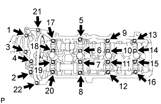
- Torque:
- for bolt 21, 22:
- 7.5 N*m{ 76 kgf*cm , 66 in.*lbf }
- for other bolt:
- 16 N*m{ 163 kgf*cm , 12 ft.*lbf }
Bring the service bolt installed in the driven sub-gear upward by turning the hexagonal portion of the camshaft with a wrench.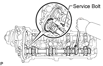
Remove the service bolt.
| 27. INSTALL REAR TIMING BELT PLATE LH |
Install the timing belt plate with the bolt.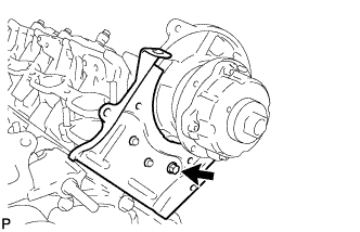
- Torque:
- 7.5 N*m{ 76 kgf*cm , 66 in.*lbf }
| 28. INSTALL REAR NO. 2 TIMING BELT PLATE LH |
Install the timing plate with the 2 bolts.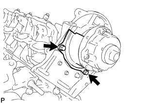
- Torque:
- 7.5 N*m{ 76 kgf*cm , 66 in.*lbf }
| 29. INSTALL REAR TIMING BELT PLATE RH |
Install the timing belt plate with the bolt.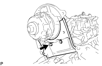
- Torque:
- 7.5 N*m{ 76 kgf*cm , 66 in.*lbf }
| 30. INSTALL REAR NO. 2 TIMING BELT PLATE RH |
Install the timing plate with the 2 bolts and stud bolt.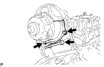
- Torque:
- 7.5 N*m{ 76 kgf*cm , 66 in.*lbf }
| 31. INSTALL CAMSHAFT TIMING PULLEY |
Align the camshaft timing tube knock pin with the knock pin groove of the timing pulley.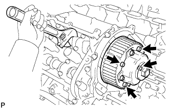
Temporarily install the 4 bolts of the camshaft timing pulley.
Hold the hexagonal portion of the camshaft with a wrench.
Using a 5 mm hexagon wrench, tighten the 4 bolts.
- Torque:
- 8.1 N*m{ 83 kgf*cm , 72 in.*lbf }
| 32. INSTALL CAMSHAFT TIMING PULLEY SUB-ASSEMBLY LH |
Align the camshaft timing tube knock pin with the knock pin groove of the timing pulley.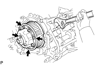
Temporarily install the 4 bolts of the camshaft timing pulley.
Hold the hexagonal portion of the camshaft with a wrench.
Using a 5 mm hexagon wrench, tighten the 4 bolts.
- Torque:
- 8.1 N*m{ 83 kgf*cm , 72 in.*lbf }
| 33. INSTALL CRANKSHAFT TIMING PULLEY |
Align the timing pulley set key with the key groove of the pulley.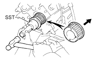
Using SST and a hammer, tap in the timing pulley with the flange side facing inward.
- SST
- 09223-46011
| 34. INSTALL NO. 2 TIMING BELT IDLER SUB-ASSEMBLY |
Install the timing belt idler with the bolt.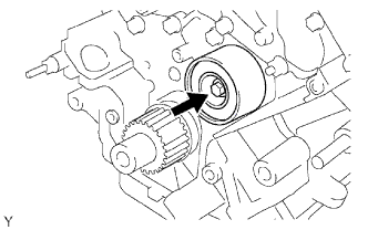
- Torque:
- 35 N*m{ 352 kgf*cm , 25 ft.*lbf }
| 35. INSTALL NO. 1 TIMING BELT IDLER SUB-ASSEMBLY |
When reusing the timing belt idler shaft, apply adhesive to 2 or 3 of the threads.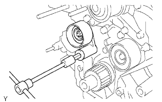
- Adhesive:
- Toyota Genuine Adhesive 1324, Three Bond 1324 or equivalent
Using a 10 mm hexagon wrench, install the plate washer and timing belt idler with the idler shaft.
- Torque:
- 35 N*m{ 352 kgf*cm , 25 ft.*lbf }
| 36. INSTALL TIMING BELT |
Set the No. 1 cylinder to TDC/compression.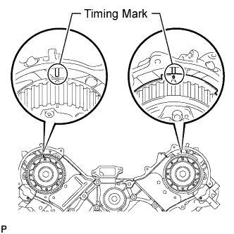
Turn the hexagonal portion of the camshaft to align the timing marks of the camshaft timing pulleys and timing belt plates.
Using the pulley bolt, turn the crankshaft to align the timing marks of the crankshaft timing pulley and oil pump body.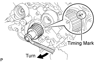
Install the timing belt.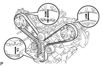
Remove any oil or water from each pulley, and keep them clean.
- NOTICE:
- Only wipe the pulleys. Do not use any cleansing agent on the pulleys.
Face the front mark (arrow) on the timing belt forward.
Align the timing marks on the timing belt and crankshaft timing pulley, and the timing belt and camshaft timing pulleys, and install the timing belt.
Install the belt tensioner.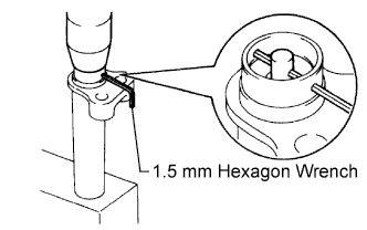
Remove the dust seal from the belt tensioner.
Using a press, slowly press in the push rod using a force of 981 to 9807 N (100 to 1000 kgf, 220.5 to 2204.7 lbf).
Align the holes of the push rod and housing, and pass a 1.5 mm hexagon wrench through the holes to keep the setting position of the push rod.
Release the press.
Install the dust seal to the belt tensioner.
Temporarily install the belt tensioner with the 2 bolts.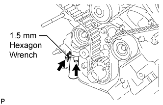
Tighten the 2 bolts.
- Torque:
- 26 N*m{ 265 kgf*cm , 19 ft.*lbf }
Using pliers, remove the 1.5 mm hexagon wrench from the timing belt tensioner.
| 37. CHECK NO. 1 CYLINDER TO TDC/COMPRESSION |
Using the pulley bolt, slowly turn the crankshaft timing pulley 2 revolutions from the TDC to TDC.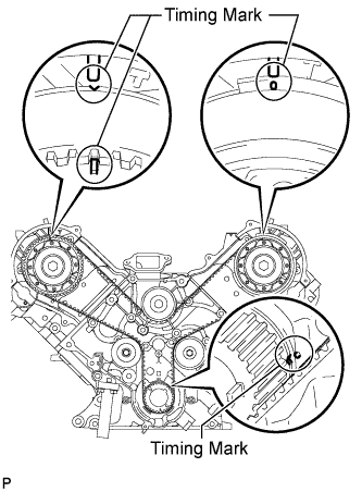
- NOTICE:
- Always turn the crankshaft timing pulley clockwise.
Check that each pulley is aligned with each timing mark as shown in the illustration.
If the timing marks are not aligned, remove the timing belt and reinstall it.
Remove the pulley bolt.
| 38. INSPECT VALVE CLEARANCE |
Inspect the valve clearance (Click here).
If the result is not as specified, adjust the valve clearance (Click here).
| 39. INSTALL CAMSHAFT POSITION SENSOR ASSEMBLY |
Install the camshaft position sensor with the bolt and stud bolt.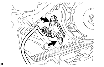
- Torque:
- 7.5 N*m{ 80 kgf*cm , 66 in.*lbf }
| 40. INSTALL SPARK PLUG TUBE GASKET |
Using a cutter knife, cut off the seal part of the removed gasket.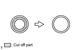
Using the removed gasket and a hammer, tap in a new gasket until it stops.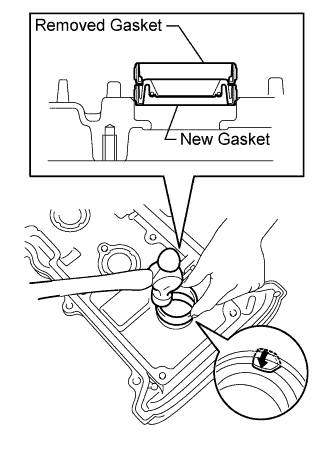
- NOTICE:
- Do not tap on the oil seal at an angle.
- HINT:
- If the removed gasket does not fit on the new one, correct the removed one with pliers.
Apply a light coat of MP grease to the lip of the gasket.
- NOTICE:
- Keep the lip free from foreign matter.
Return the 8 ventilation case claws to the original positions.
| 41. INSTALL CYLINDER HEAD COVER SUB-ASSEMBLY |
Install a new gasket to the cylinder head cover.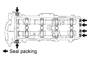
Apply seal packing to the cylinder head as shown in the illustration.
- Seal packing:
- Toyota Genuine Seal Packing Black, Three Bond 1207B or equivalent
- NOTICE:
- Remove any oil from the contact surface.
- Install the cylinder head cover within 3 minutes after applying seal packing.
- Remove any oil from the contact surface.
Install the cylinder head cover with the 9 bolts. Uniformly tighten the bolts in several steps.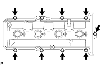
- Torque:
- 6.0 N*m{ 61 kgf*cm , 53 in.*lbf }
| 42. INSTALL CYLINDER HEAD COVER SUB-ASSEMBLY LH |
Install a new gasket to the cylinder head cover.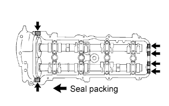
Apply seal packing to the cylinder head as shown in the illustration.
- Seal packing:
- Toyota Genuine Seal Packing Black, Three Bond 1207B or equivalent
- NOTICE:
- Remove any oil from the contact surface.
- Install the cylinder head cover within 3 minutes after applying seal packing.
- Remove any oil from the contact surface.
Install the cylinder head cover with the 9 bolts. Uniformly tighten the bolts in several steps.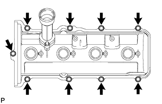
- Torque:
- 6.0 N*m{ 61 kgf*cm , 53 in.*lbf }
| 43. INSTALL OIL FILLER CAP HOUSING |
Install a new gasket and the housing with the 2 nuts.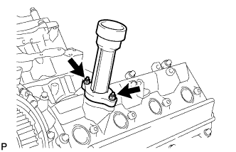
- Torque:
- 7.5 N*m{ 76 kgf*cm , 66 in.*lbf }
| 44. INSTALL OIL FILLER CAP SUB-ASSEMBLY |
Install a new gasket to the oil filler cap.
Install the oil filler cap.
| 45. INSTALL SPARK PLUG |
Install the 8 spark plugs.
- Torque:
- 18 N*m{ 184 kgf*cm , 13 ft.*lbf }
| 46. INSTALL NO. 1 ENGINE HANGER |
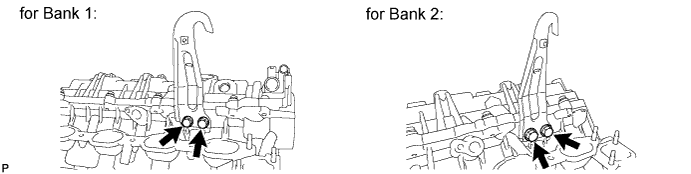
Install the engine hanger with the 2 bolts.
- Torque:
- 37 N*m{ 377 kgf*cm , 27 ft.*lbf }
| 47. INSTALL NO. 1 CRANKSHAFT POSITION SENSOR PLATE |
Install the sensor plate as shown in the illustration.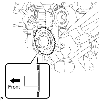
- NOTICE:
- Take care not to install the sensor plate in a wrong direction.
| 48. INSTALL TIMING BELT COVER SPACER |
Install the cover spacer and gasket.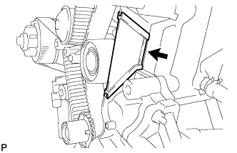
| 49. INSTALL NO. 1 TIMING BELT COVER |
Install the timing belt cover with the 4 bolts.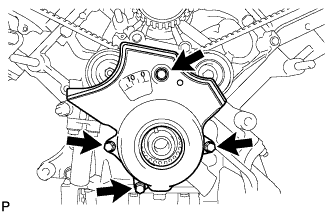
- Torque:
- 7.5 N*m{ 76 kgf*cm , 66 in.*lbf }
| 50. INSTALL CRANKSHAFT DAMPER SUB-ASSEMBLY |
Align the pulley set key with the key groove of the crankshaft damper.
Using SST, hold the crankshaft pulley and install the pulley bolt.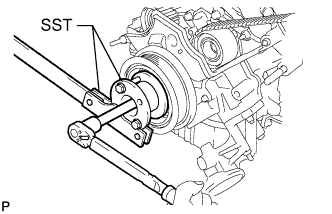
- SST
- 09213-70011
(09213-70020)
09330-00021 (09330-00030)
- Torque:
- 245 N*m{ 2498 kgf*cm , 181 ft.*lbf }
| 51. INSTALL FAN BRACKET SUB-ASSEMBLY |
Install the fan bracket with the 2 bolts and 2 nuts.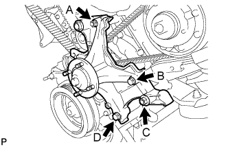
- Torque:
- for nut A, bolt B:
- 16 N*m{ 163 kgf*cm , 12 ft.*lbf }
- for nut C, bolt D:
- 32 N*m{ 326 kgf*cm , 24 ft.*lbf }
| 52. INSTALL V-RIBBED BELT TENSIONER ASSEMBLY |
Install the belt tensioner with the bolt and 2 nuts.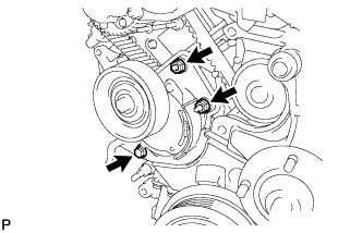
- Torque:
- 16 N*m{ 163 kgf*cm , 12 ft.*lbf }
| 53. INSTALL NO. 2 TIMING BELT COVER SUB-ASSEMBLY |
Install the timing belt cover and fit the 2 claws into each part.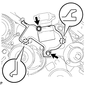
Install the 2 bolts.
- Torque:
- 16 N*m{ 163 kgf*cm , 12 ft.*lbf }
| 54. INSTALL NO. 3 TIMING BELT COVER SUB-ASSEMBLY LH |
Pass the camshaft position sensor wire through the cover hole.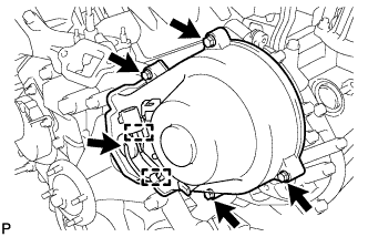
Install the timing belt cover with the 4 bolts.
- Torque:
- 7.5 N*m{ 76 kgf*cm , 66 in.*lbf }
Install the wire grommet to the timing belt cover.
Connect the sensor connector.
Install the sensor wire to the 2 wire clamps on the cover.
Connect the engine wire to the 3 wire clamps.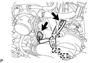
Connect the camshaft timing oil control valve connector and control motor connector.
| 55. INSTALL NO. 3 TIMING BELT COVER SUB-ASSEMBLY RH |
Install the timing belt cover with the 3 bolts and nut.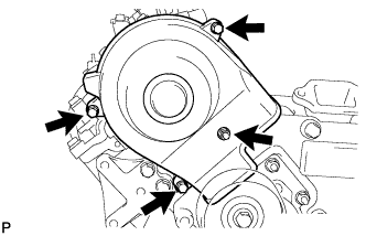
- Torque:
- 7.5 N*m{ 76 kgf*cm , 66 in.*lbf }
| 56. INSTALL NO. 2 IDLER PULLEY SUB-ASSEMBLY |
Install the idler pulley and cover plate with the bolt.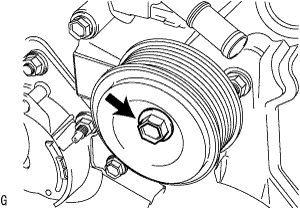
- Torque:
- 39 N*m{ 398 kgf*cm , 29 ft.*lbf }