B2282 Vehicle Speed Signal Malfunction
Diagnostic trouble codes · Vehicles built from Jan 2012
Also covers:
- B2283 Vehicle Speed Sensor Malfunction
Versions by build date: Sep 2011 – Dec 2011 from Jan 2012
DESCRIPTION
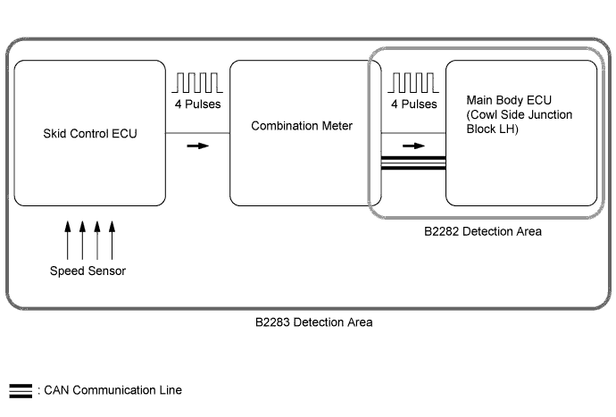
The main body ECU and the combination meter are connected with a cable and the CAN communication line. DTC B2282 is stored when signals, transmitted through the cable and communication line, do not match.| DTC Code |
Detection Condition |
Trouble Area |
| B2282 |
When the following conditions are met:
|
|
| DTC Code |
Detection Condition |
Trouble Area |
| B2283 |
When both of the conditions below are met:
|
|

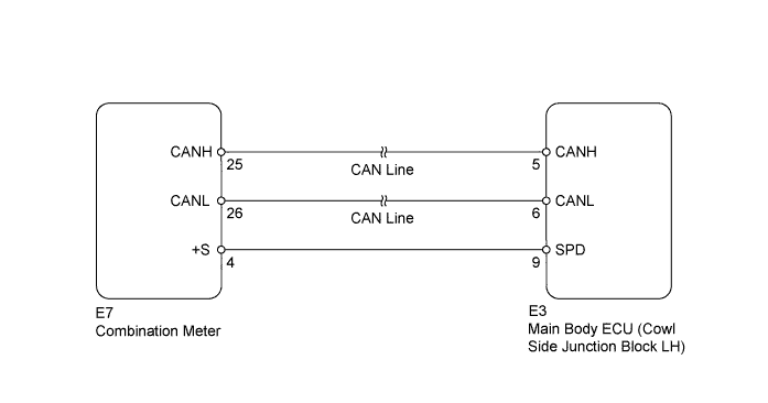
WIRING DIAGRAM
INSPECTION PROCEDURE
| 1. READ VALUE USING INTELLIGENT TESTER (VEHICLE SPEED SIGNAL) |

Use the Data List to check if the vehicle speed signal is functioning properly.
Main Body Tester Display
Measurement Item/Range
Normal Condition
Diagnostic Note
Vehicle Speed Signal
Vehicle speed signal/STOP or RUN
STOP: Vehicle stopped
RUN: Vehicle running
-
Result Result
Proceed to
Display on the intelligent tester does not change according to vehicle condition
A
Display on the intelligent tester changes according to vehicle condition
B
|
|
||||

| A | |
 |
| 2. CHECK HARNESS AND CONNECTOR (MAIN BODY ECU - COMBINATION METER) |
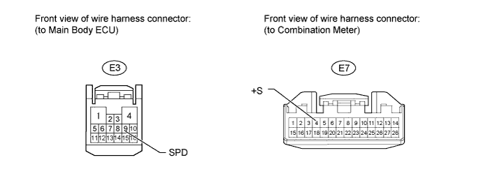
Disconnect the E3 main body ECU connector.
Disconnect the E7 combination meter connector.
Measure the resistance according to the value(s) in the table below.
- Standard Resistance:
Tester Connection
Condition
Specified Condition
E3-9 (SPD) - E7-4 (+S)
Always
Below 1 Ω
E3-9 (SPD) or E7-4 (+S) - Body ground
Always
10 kΩ or higher
|
|
||||
| OK | |
|
| 3. REPLACE MAIN BODY ECU |
Temporarily replace the main body ECU with a new or normally functioning one.
Check whether DTC B2282 and B2283 are output.
Result Result
Proceed to
DTC not output
A
DTC output (w/ Multi-information Display)
B
DTC output (w/o Multi-information Display)
C
|
|
||||
|
|
||||
| A | ||
 |
||
| ||