INSTALLATION
Removal / installation · Vehicles built Sep 2011 – Dec 2011
Versions by build date: Sep 2011 – Dec 2011 from Jan 2012
| 1.
INSTALL GLOW PLUG ASSEMBLY |
 |
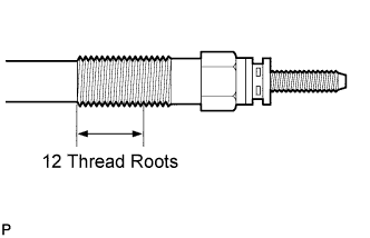
- Apply adhesive to 3 or more thread roots in the area shown in the illustration.
- Adhesive:
- Toyota Genuine Adhesive 1324, Three Bond 1324 or equivalent
- Using a 10 mm deep socket wrench, install the 8 glow plugs.
-
Torque:
- 12 N*m{
125 kgf*cm
, 9 ft.*lbf
}
| 2.
INSTALL NO. 1 GLOW PLUG CONNECTOR |
|
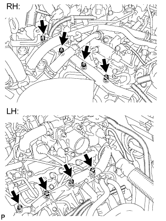
Install the 2 glow plug connectors by uniformly tightening the 8 nuts.
-
Torque:
- 2.2 N*m{
22 kgf*cm
, 19 in.*lbf
}
Install the 8 screw grommets.
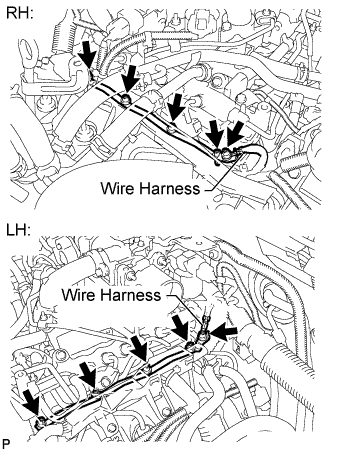
Connect the 2 wire harnesses with the 2 nuts and 2 screw grommets.
-
Torque:
- 4.0 N*m{
41 kgf*cm
, 35 in.*lbf
}
| 3.
CONNECT ENGINE WIRE |
|
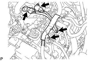
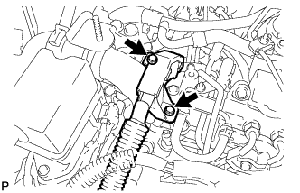
- Connect the 2 connectors.
Connect the engine wire with the 2 bolts.
-
Torque:
- 13 N*m{
133 kgf*cm
, 10 ft.*lbf
}
- Connect the engine wire with the 2 bolts.
-
Torque:
- 13 N*m{
133 kgf*cm
, 10 ft.*lbf
}
| 4.
CONNECT NO. 4 WATER BY-PASS PIPE |
|
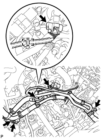
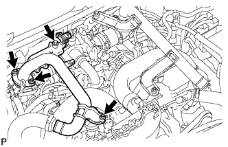
- Connect the water by-pass pipe with the 4 bolts and nut.
-
Torque:
- 10 N*m{
102 kgf*cm
, 7 ft.*lbf
}
Attach the clamp and connect the connector.
| 5.
INSTALL NO. 1 AIR CLEANER PIPE SUB-ASSEMBLY
|
|
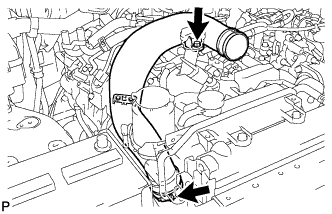
- Connect the No. 1 air cleaner pipe to the No. 1 intake air connector pipe.
Install the pipe with the bolt.
-
Torque:
- 21 N*m{
214 kgf*cm
, 15 ft.*lbf
}
Tighten the hose clamp.
-
Torque:
- 6.3 N*m{
64 kgf*cm
, 56 in.*lbf
}
| 6.
INSTALL NO. 2 AIR CLEANER PIPE SUB-ASSEMBLY
|
|
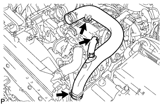
- Connect the No. 2 air cleaner pipe to the No. 2 intake air connector pipe.
Connect the ventilation hose to the oil separator.
Install the pipe with the bolt.
-
Torque:
- 21 N*m{
214 kgf*cm
, 15 ft.*lbf
}
Tighten the hose clamp.
-
Torque:
- 6.3 N*m{
64 kgf*cm
, 56 in.*lbf
}
| 7.
INSTALL NO. 2 AIR HOSE
|
|
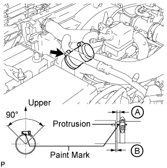
- Connect the No. 2 air hose with the hose clamp.
-
Torque:
- 6.3 N*m{
64 kgf*cm
, 56 in.*lbf
}
- HINT:
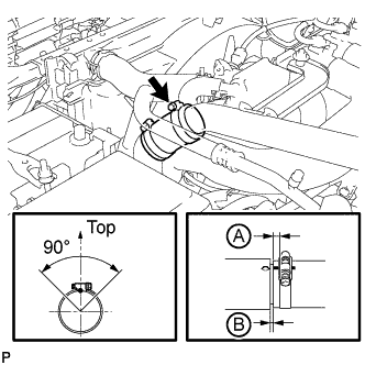
- Align the paint mark of the air hose with the protrusion and push in the air hose so that distance B is 0 to 3 mm (0 to 0.118 in.).
- Position the clamp so that distance A is 2 to 6 mm (0.0787 to 0.236 in.).
- Make sure the direction of the hose clamp is as shown in the illustration.
| 8.
INSTALL NO. 1 AIR HOSE
|
|
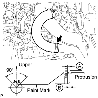
- Connect the No. 1 air hose with the hose clamp.
-
Torque:
- 6.3 N*m{
64 kgf*cm
, 56 in.*lbf
}
- HINT:
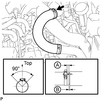
- Align the paint mark of the air hose with the protrusion and push in the air hose so that distance B is 0 to 3 mm (0 to 0.118 in.).
- Position the clamp so that distance A is 2 to 6 mm (0.0787 to 0.236 in.).
- Make sure the direction of the hose clamp is as shown in the illustration.
| 9.
INSTALL INTAKE AIR CONNECTOR
|
|
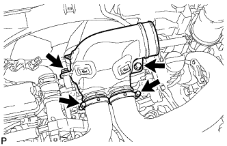
- Connect the intake air connector to the No. 1 and No. 2 air cleaner pipes.
Install the connector with the 2 bolts.
-
Torque:
- 21 N*m{
214 kgf*cm
, 15 ft.*lbf
}
Tighten the 2 hose clamps.
-
Torque:
- 6.3 N*m{
64 kgf*cm
, 56 in.*lbf
}
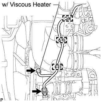
- Attach the 3 wire harness clamps.
w/o Viscous Heater:
Connect the connector to the water temperature sensor.
w/ Viscous Heater:
Connect the 2 connectors to the water temperature sensor and viscous with magnet clutch heater.
| 10.
TEMPORARILY INSTALL NO. 1 AIR CLEANER HOSE
|
|
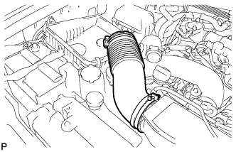
- Temporarily install the air cleaner hose to the intake air connector.
| 11.
INSTALL AIR CLEANER CAP SUB-ASSEMBLY
|
|
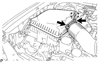
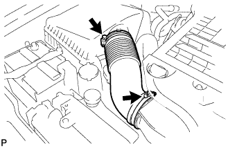
- Connect the air cleaner cap to the air cleaner hose, and install the air cleaner cap with the 4 clamps.
Connect the mass air flow meter connector and attach the wire harness clamp to the air cleaner cap.
Attach the wire harness clamp.
- Align the protrusion of air cleaner cap and concave portion of air cleaner hose.
Tighten the 2 hose clamps.
-
Torque:
- 5.0 N*m{
51 kgf*cm
, 44 in.*lbf
}
| 12.
INSTALL AIR TUBE SUB-ASSEMBLY LH
|
|
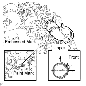
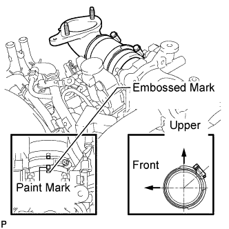
Install the air tube to the throttle body.
Align the embossed mark of the throttle body with the paint mark of the No. 4 air hose.
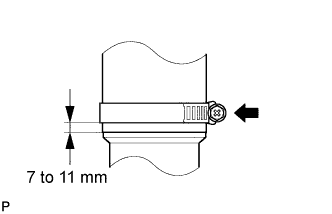
- Tighten the hose clamp so that it is 7 to 11 mm (0.276 to 0.433 in.) from the end of the hose as shown in the illustration.
-
Torque:
- 6.3 N*m{
64 kgf*cm
, 56 in.*lbf
}
| 13.
INSTALL AIR TUBE SUB-ASSEMBLY RH
|
|
Install the air tube to the throttle body.
Align the embossed mark of the throttle body with the paint mark of the No. 4 air hose.
- Tighten the hose clamp so that it is 7 to 11 mm (0.276 to 0.433 in.) from the end of the hose as shown in the illustration.
-
Torque:
- 6.3 N*m{
64 kgf*cm
, 56 in.*lbf
}
| 14.
INSTALL NO. 2 COOL AIR INLET (w/o Intercooler)
|
|
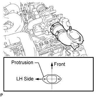
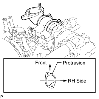
- Install a new gasket to the air tube LH.
- HINT:
- Install the gasket with the protrusion facing as shown in the illustration.
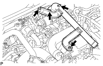
- Install the No. 2 cool air inlet with the 3 nuts and bolt.
-
Torque:
- 21 N*m{
214 kgf*cm
, 15 ft.*lbf
}
- Connect the No. 2 air hose to the No. 2 cool air inlet.
Tighten the No. 2 air hose clamp.
-
Torque:
- 6.3 N*m{
64 kgf*cm
, 56 in.*lbf
}
- HINT:
- Align the paint mark of the air hose with the protrusion and push on the air hose so that distance B is 0 to 3 mm (0 to 0.118 in.).
- Position the clamp so that distance A is 2 to 6 mm (0.0787 to 0.236 in.).
- Make sure the direction of the hose clamp is as shown in the illustration.
| 15.
INSTALL NO. 1 COOL AIR INLET (w/o Intercooler)
|
|
- Install a new gasket to the air tube RH.
- HINT:
- Install the gasket with the protrusion facing as shown in the illustration.
- Install the No. 1 cool air inlet with the 3 nuts and bolt.
-
Torque:
- 21 N*m{
214 kgf*cm
, 15 ft.*lbf
}
Connect the vacuum hose, intake air temperature sensor connector and turbo pressure sensor connector.
- Connect the No. 1 air hose to the No. 1 cool air inlet.
Tighten the No. 1 air hose clamp.
-
Torque:
- 6.3 N*m{
64 kgf*cm
, 56 in.*lbf
}
- HINT:
- Align the paint mark of the air hose with the protrusion and push on the air hose so that distance B is 0 to 3 mm (0 to 0.118 in.).
- Position the clamp so that distance A is 2 to 6 mm (0.0787 to 0.236 in.).
- Make sure the direction of the hose clamp is as shown in the illustration.
| 16.
INSTALL INTERCOOLER ASSEMBLY (w/ Intercooler) |
|
Install the intercooler (Click here).