INSTALLATION
Removal / installation · Vehicles built Sep 2011 – Dec 2011
Versions by build date: Sep 2011 – Dec 2011 from Jan 2012
| 1.
INSTALL VACUUM PUMP ASSEMBLY |
 |
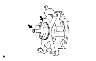
- Apply engine oil to 2 new O-rings.
Install the 2 O-rings to the vacuum pump.
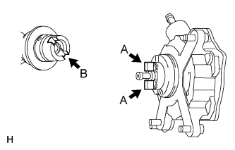
- Install the vacuum pump so that the coupling teeth of the vacuum pump (labeled A) and the groove of the camshaft (labeled B) are aligned.
- NOTICE:
- Be careful not to damage the O-ring.
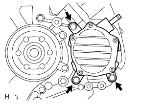
- Install the vacuum pump with the 3 bolts.
-
Torque:
- 21 N*m{
214 kgf*cm
, 15 ft.*lbf
}
- NOTICE:
- Confirm that the vacuum pump is not at an angle, and that there is no clearance between the fitting surfaces.
| 2.
CONNECT UNION TO CONNECTOR TUBE HOSE |
|
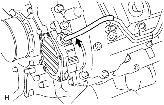
- Connect the hose to the vacuum pump.
| 3.
INSTALL NO. 2 IDLER PULLEY BRACKET (w/ Viscous Heater)
|
|
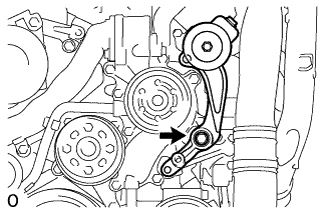
- Temporarily install the No. 2 idler pulley bracket with the bolt.
Temporarily install the 2 bolts to the No. 2 idler pulley bracket bolt hole.
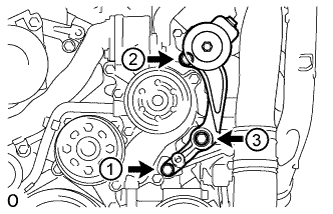
- Uniformly tighten the 3 bolts of the No. 2 idler pulley bracket in the order shown in the illustration.
-
Torque:
- 49 N*m{
495 kgf*cm
, 36 ft.*lbf
}
| 4.
INSTALL NO. 2 IDLER PULLEY (w/ Viscous Heater)
|
|
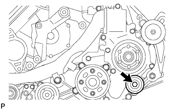
- Install the collar, No. 2 idler pulley and cover with the bolt.
-
Torque:
- 49 N*m{
495 kgf*cm
, 36 ft.*lbf
}
| 5.
INSTALL V-RIBBED BELT (w/ Viscous Heater)
|
|
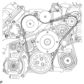
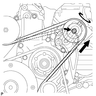
- Install the V-ribbed belt as shown in the illustration.
- Temporarily install the lock nut, and turn the bolt clockwise.
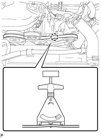
- Using a belt tension gauge, adjust belt tension.
- Standard Belt Tension:
Item
|
Specified Condition
|
New belt
|
400 to 650 N (41 to 66 kgf, 89.9 to 146.1 lbf)
|
Used belt
|
300 to 500 N (31 to 51 kgf, 67.4 to 112.4 lbf)
|
- HINT:
- A "new belt" is a belt which has been used for less than 5 minutes on a running engine.
- A "used belt" is a belt which has been used on a running engine for 5 minutes or more.
- After installing a new belt, run the engine for approximately 5 minutes and then recheck the tension.
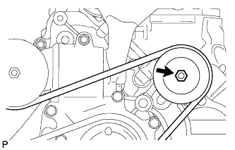
- Tighten the nut.
-
Torque:
- 40 N*m{
408 kgf*cm
, 30 ft.*lbf
}
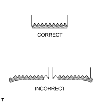
- Check that the belt fits properly in the ribbed grooves.
- HINT:
- Check with your hand to confirm that the belt has not slipped out of the groove on the bottom of the pulley.
- If it has slipped out, replace the V-ribbed belt. Install a new V-ribbed belt.
| 6.
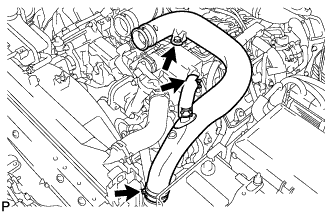
INSTALL NO. 2 AIR CLEANER PIPE SUB-ASSEMBLY
|
|
- Connect the No. 2 air cleaner pipe to the No. 2 intake air connector pipe.
Connect the ventilation hose to the oil separator.
Install the pipe with the bolt.
-
Torque:
- 21 N*m{
214 kgf*cm
, 15 ft.*lbf
}
Tighten the hose clamp.
-
Torque:
- 6.3 N*m{
64 kgf*cm
, 56 in.*lbf
}
| 7.
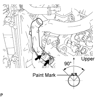
INSTALL NO. 4 AIR TUBE
|
|
- Install the No. 4 air tube with the bolt.
-
Torque:
- 21 N*m{
214 kgf*cm
, 15 ft.*lbf
}
Tighten the hose clamp.
-
Torque:
- 6.3 N*m{
64 kgf*cm
, 56 in.*lbf
}
- HINT:
- Make sure the direction of the hose clamp is as shown in the illustration.
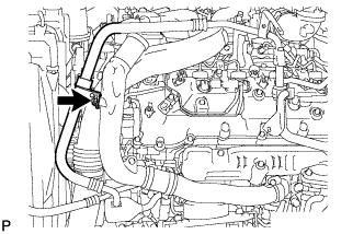
- Install the suction hose with the bolt.
-
Torque:
- 9.8 N*m{
100 kgf*cm
, 87 in.*lbf
}
| 8.
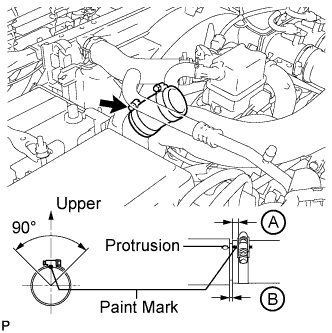
INSTALL NO. 2 AIR HOSE
|
|
- Connect the No. 2 air hose with the hose clamp.
-
Torque:
- 6.3 N*m{
64 kgf*cm
, 56 in.*lbf
}
- HINT:
- Align the paint mark of the air hose with the protrusion and push in the air hose so that distance B is 0 to 3 mm (0 to 0.118 in.).
- Position the clamp so that distance A is 2 to 6 mm (0.0787 to 0.236 in.).
- Make sure the direction of the hose clamp is as shown in the illustration.
| 9.
INSTALL INTERCOOLER ASSEMBLY |
|
Install the intercooler assembly (Click here).
| 10.
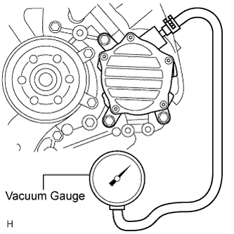
CHECK VACUUM PUMP OPERATION
|
|
Disconnect the union to connector tube hose from the vacuum pump.
- Connect a vacuum gauge to the vacuum pump.
Start the engine and warm it up for more than 2 minutes.
With the engine idling, measure the negative pressure of the vacuum pump.
- Standard Pressure:
- More than 86.7 kPa (650 mmHg, 25.6 in.Hg)
- HINT:
- It is necessary to replace the vacuum pump assembly every 200000 km (124000 miles).
Remove the vacuum gauge from the vacuum pump.
Connect the union to connector tube hose to the vacuum pump.