14.
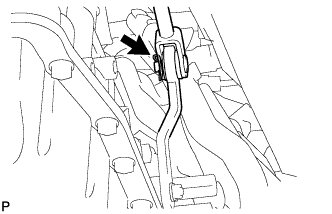
DISCONNECT FLOOR SHIFT GEAR SHIFTING ROD SUB-ASSEMBLY
Remove the clip and pin, and disconnect the gear shifting rod from the transmission control shaft lever RH.
15.
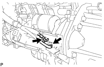
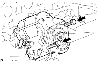
REMOVE STARTER ASSEMBLY (for 1.4 kW Type)
Disconnect the terminal cap.
Remove the nut and disconnect the starter wire.
Disconnect the starter connector.
Remove the 2 bolts and starter.
16.
REMOVE DRIVE PLATE AND TORQUE CONVERTER CLUTCH SETTING BOLT
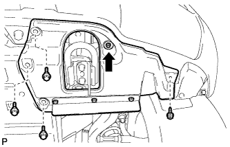
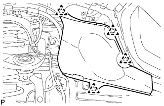
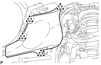
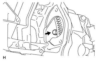
Remove the flywheel housing side cover.
Turn the crankshaft to gain access to the 6 bolts and remove each bolt while holding the crankshaft pulley setting bolt with a wrench.
17.
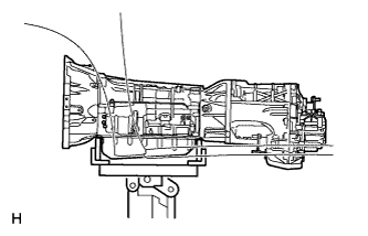
SUPPORT AUTOMATIC TRANSMISSION ASSEMBLY
Support the transmission with a transmission jack. Lift the transmission slightly from the crossmember.
18.
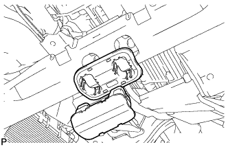
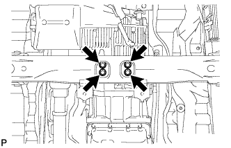
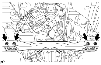
REMOVE NO. 2 FRAME CROSSMEMBER SUB-ASSEMBLY
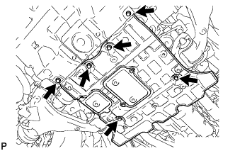
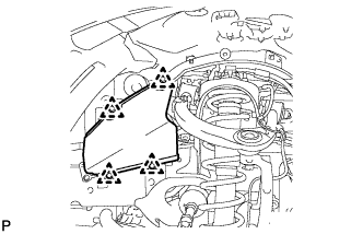
Remove the engine mounting hole cover.
Remove the 4 bolts of the rear engine mounting insulator.
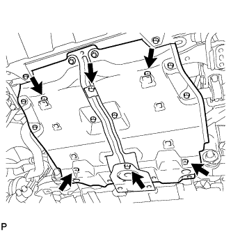
Remove the 4 nuts, 4 bolts and frame crossmember.
19.
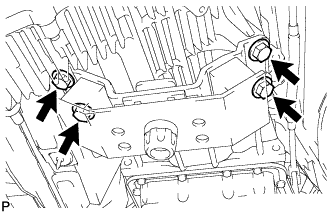
REMOVE REAR NO. 1 ENGINE MOUNTING INSULATOR
Remove the 4 bolts and rear engine mounting insulator from the transmission.
20.
DISCONNECT WIRE HARNESS AND CONNECTOR
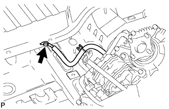
Remove the bolt and disconnect the ground cable.
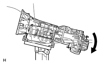
Tilt the transmission downward.
NOTICE:
Make sure the cooling fan does not contact the fan shroud.
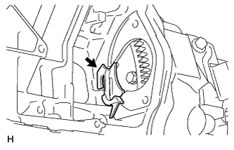
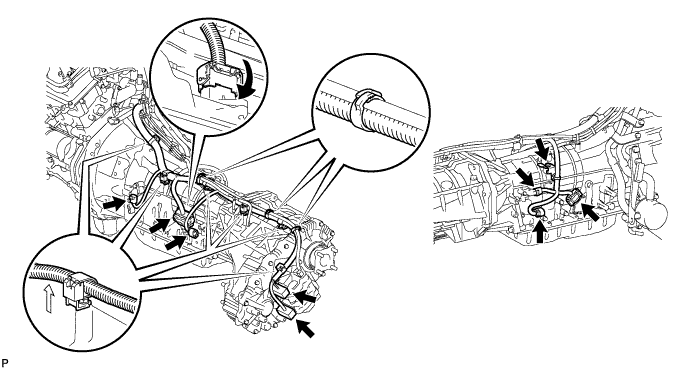
Disconnect the park/neutral position switch connector, transmission wire connector, 2 transmission speed sensor connectors and 2 transfer control side connectors.
HINT:
Detach the claw, press down the lever, and then disconnect the transmission wire connector.
Disconnect the 2 connector clamps and 6 harness clamps.
Remove the bolt and disconnect the wire harness.
21.
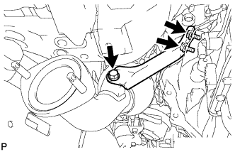
REMOVE MANIFOLD STAY
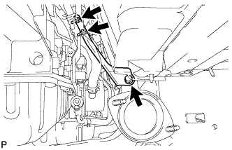
Remove the 3 bolts and stay.
22.
REMOVE NO. 2 MANIFOLD STAY
Remove the 3 bolts and stay.
23.
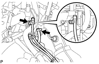
DISCONNECT BREATHER PLUG HOSE
Disconnect the breather plug hose and detach the transfer breather hose.
24.
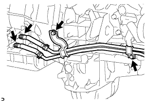
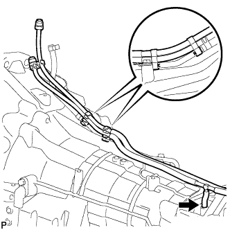
DISCONNECT OIL COOLER TUBE
Remove the 2 bolts and disconnect the 2 hoses from the transmission, and separate the oil cooler tube from the engine.
25.
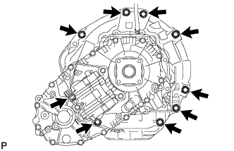
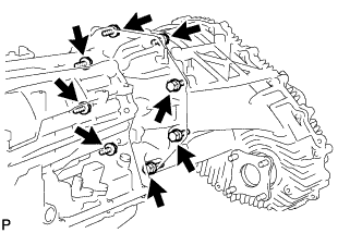
REMOVE AUTOMATIC TRANSMISSION ASSEMBLY
Remove the 9 bolts and transmission.
NOTICE:
Do not use excess force when prying the transmission assembly.
26.
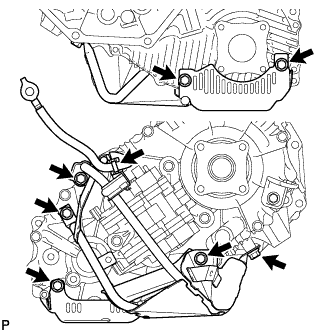
REMOVE TRANSFER ASSEMBLY
Detach the 2 breather hose clamps from the automatic transmission breather tube.
Disconnect the clamp of the ground cable from the transfer case lower protector.
Remove the 7 bolts and transfer case lower protector.