CALIBRATION
Troubleshooting · Vehicles built Sep 2011 – Dec 2011
Versions by build date: Sep 2011 – Dec 2011 from Jan 2012
| DESCRIPTION |
| Replacement/Adjustment Part |
Necessary Operation |
| Master cylinder solenoid (Skid control ECU) |
G sensor zero point calibration |
| G sensor |
1. Clearing zero point calibration data 2. G sensor zero point calibration |
| CLEAR ZERO POINT CALIBRATION (SST CHECK WIRE) |
Turn the ignition switch to ON.
Using SST, connect and disconnect terminals 12 (TS) and 4 (CG) of the DLC3 4 times or more within 8 seconds.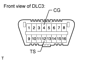

- SST
- 09843-18040
Check that the ABS warning light outputs the normal system code.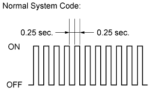
Using a check wire, perform zero point calibration of the G sensor.
| PERFORM ZERO POINT CALIBRATION OF G SENSOR (SST CHECK WIRE) |
- NOTICE:
- While obtaining the zero point, do not vibrate the vehicle by tilting, moving or shaking it. Keep it stationary and do not start the engine.
- Choose a level surface with an inclination of less than 1°.
- While obtaining the zero point, do not vibrate the vehicle by tilting, moving or shaking it. Keep it stationary and do not start the engine.
Procedures for Test Mode:
Turn the ignition switch off.
for A/T:
Move the shift lever to P.- NOTICE:
- DTC C1336/98 will be stored if the shift lever is not in P (Click here).
for M/T:
Pull the parking brake lever.- NOTICE:
- DTC C1336/98 will be stored if the parking brake lever is not pulled (Click here).
Using SST, connect terminals 12 (TS) and 4 (CG) of the DLC3.
- SST
- 09843-18040
Check that the steering wheel is centered.
Turn the ignition switch to ON.
Keep the vehicle stationary on a level surface for 2 seconds or more.
Check that the ABS warning light is blinking in test mode.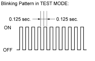
- NOTICE:
- The ABS warning light stays on when obtaining the zero point.
- HINT:
- If the ABS warning light does not blink, perform the zero point calibration again.
- The zero point calibration is performed only once after the system enters test mode.
- Calibration cannot be performed again until the stored data is cleared once.
- If the ABS warning light does not blink, perform the zero point calibration again.
| CLEAR ZERO POINT CALIBRATION (INTELLIGENT TESTER) |
Connect the intelligent tester to the DLC3.
Turn the ignition switch to ON.
Turn the intelligent tester on.
Enter the following menus: Chassis / ABS/VSC/TRC / Utility / Reset Memory.
Using the intelligent tester, perform zero point calibration of the G sensor.
| PERFORM ZERO POINT CALIBRATION OF G SENSOR (INTELLIGENT TESTER) |
- NOTICE:
- While obtaining the zero point, do not vibrate the vehicle by tilting, moving or shaking it. Keep it stationary and do not start the engine.
- Choose a level surface with an inclination of less than 1°.
- While obtaining the zero point, do not vibrate the vehicle by tilting, moving or shaking it. Keep it stationary and do not start the engine.
Procedures for Test Mode:
Turn the ignition switch off.
for A/T:
Move the shift lever to P.- NOTICE:
- DTC C1336/98 will be stored if the shift lever is not in P (Click here).
for M/T:
Pull the parking brake lever.- NOTICE:
- DTC C1336/98 will be stored if the parking brake lever is not pulled (Click here).
Check that the steering wheel is centered.
Connect the intelligent tester to the DLC3.
Turn the ignition switch to ON.
Turn the intelligent tester on.
Enter the following menus: Chassis / ABS/VSC/TRC / Utility / Test Mode.
Keep the vehicle stationary on a level surface for 2 seconds or more.
Check that the ABS warning light is blinking in test mode.
- NOTICE:
- The ABS warning light stays on when obtaining the zero point.
- HINT:
- If the ABS warning light does not blink, perform the zero point calibration again.
- The zero point calibration is performed only once after the system enters test mode.
- Calibration cannot be performed again until the stored data is cleared once.
- If the ABS warning light does not blink, perform the zero point calibration again.