2.
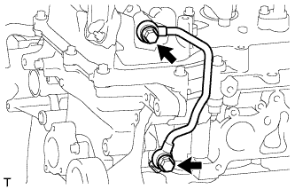
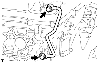
REMOVE AIR TUBE (w/ Secondary Air Injection System)
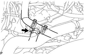
Disconnect the No. 3 air hose.
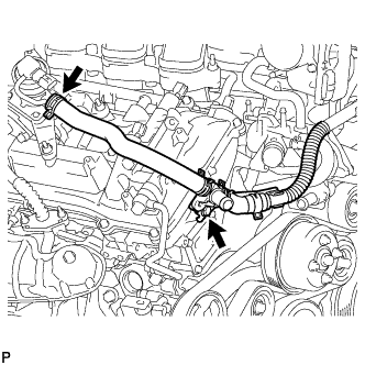
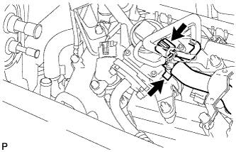
for Bank 1 Side: Remove the bolt and disconnect the air tube assembly from the emission control valve set.
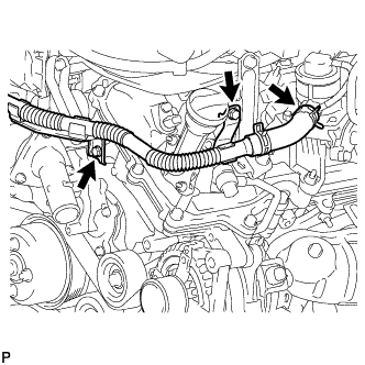
for Bank 2 Side: Remove the 2 bolts and disconnect the air tube assembly from the No. 2 emission control valve set.
3.
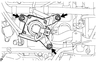
REMOVE NO. 1 EMISSION CONTROL VALVE SET (w/ Secondary Air Injection System)
Disconnect the No. 1 emission control valve set connector.
Disconnect the No. 1 air hose from the No. 1 emission control valve set.
Remove the 3 nuts and No. 1 emission control valve set.
4.
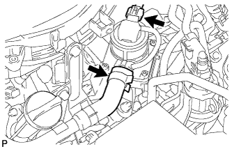
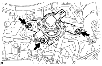
REMOVE NO. 2 EMISSION CONTROL VALVE SET (w/ Secondary Air Injection System)
Disconnect the No. 2 emission control valve set connector.
Disconnect the No. 3 air hose.
Remove the 3 nuts and No. 2 emission control valve set.
5.
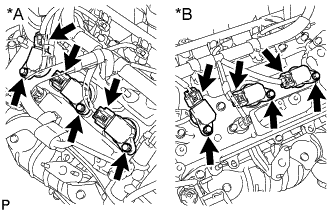
REMOVE IGNITION COIL ASSEMBLY
Disconnect the 6 ignition coil connectors.
Text in Illustration
*A
Bank 1
*B
Bank 2
Remove the 6 bolts and 6 ignition coils.
6.
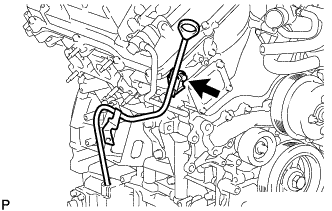
REMOVE ENGINE OIL LEVEL DIPSTICK GUIDE
Remove the engine oil level dipstick.
Remove the bolt and engine oil level dipstick guide.
Remove the O-ring from the engine oil level dipstick guide.
7.
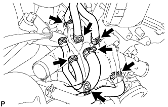
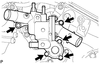
REMOVE WATER INLET HOUSING
Disconnect the throttle body connector.
Disconnect the 5 water by-pass hoses.
Disconnect the oil cooler hose.
Disconnect the No. 2 oil cooler hose.
Remove the 5 bolts and water inlet.
Remove the O-ring from the water outlet pipe.
Remove the gasket from the water pump.
8.
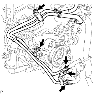
REMOVE WATER BY-PASS PIPE SUB-ASSEMBLY
Disconnect the 2 hoses.
Remove the 3 bolts and water by-pass pipe.
9.
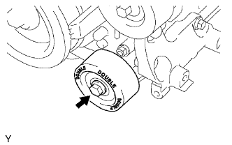
REMOVE NO. 1 IDLER PULLEY SUB-ASSEMBLY
Remove the bolt and No. 1 idler pulley.
10.
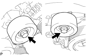
REMOVE NO. 2 IDLER PULLEY SUB-ASSEMBLY
Remove the 2 bolts and 2 No. 2 idler pulleys.
11.
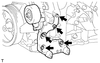
REMOVE V-RIBBED BELT TENSIONER ASSEMBLY
Remove the 5 bolts and V-ribbed belt tensioner.
12.
REMOVE OIL FILTER ELEMENT
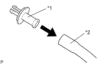
Connect a hose with an inside diameter of 15 mm (0.591 in.) to the pipe.
Text in Illustration
*1
Pipe
*2
Hose
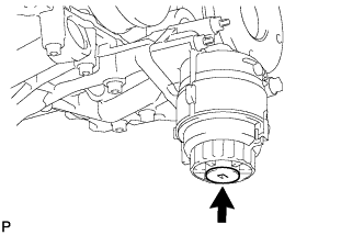
Remove the oil filter drain plug.
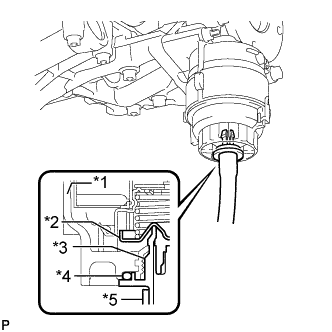
Install the pipe to the oil filter cap.
Text in Illustration
*1
Cap
*2
Valve
*3
Pipe
*4
O-Ring
*5
Hose
NOTICE:
If the O-ring is removed with the drain plug, install the O-ring together with the pipe.
HINT:
Use a container to catch the draining oil.
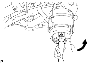
Check that oil is drained from the oil filter. Then, disconnect the pipe and remove the O-ring as shown in the illustration.
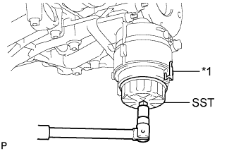
Using SST, remove the oil filter cap.
SST
09228-06501
Text in Illustration
*1
Oil Filter Bracket Clip
NOTICE:
Do not remove the oil filter bracket clip.
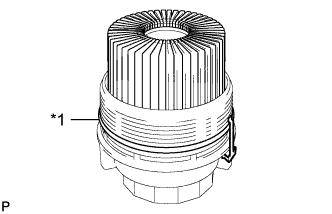
Remove the oil filter element and O-ring from the oil filter cap.
Text in Illustration
*1
O-Ring
NOTICE:
Be sure to remove the O-ring (for the cap) by hand, without using any tools, to prevent damage to the groove for the O-ring in the cap.
13.
REMOVE OIL FILTER BRACKET
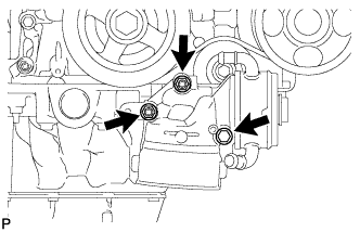
Remove the 2 nuts, bolt, oil filter bracket and gasket.
14.
REMOVE CRANKSHAFT PULLEY
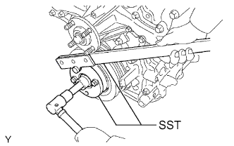
Using SST, hold the crankshaft pulley and loosen the pulley bolt. Continue to loosen the bolt until only 2 or 3 threads are screwed into the crankshaft.
SST
09213-54015
(91651-60855)
09330-00021
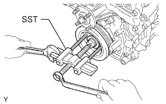
Using the pulley set bolt and SST, remove the crankshaft pulley and pulley bolt.